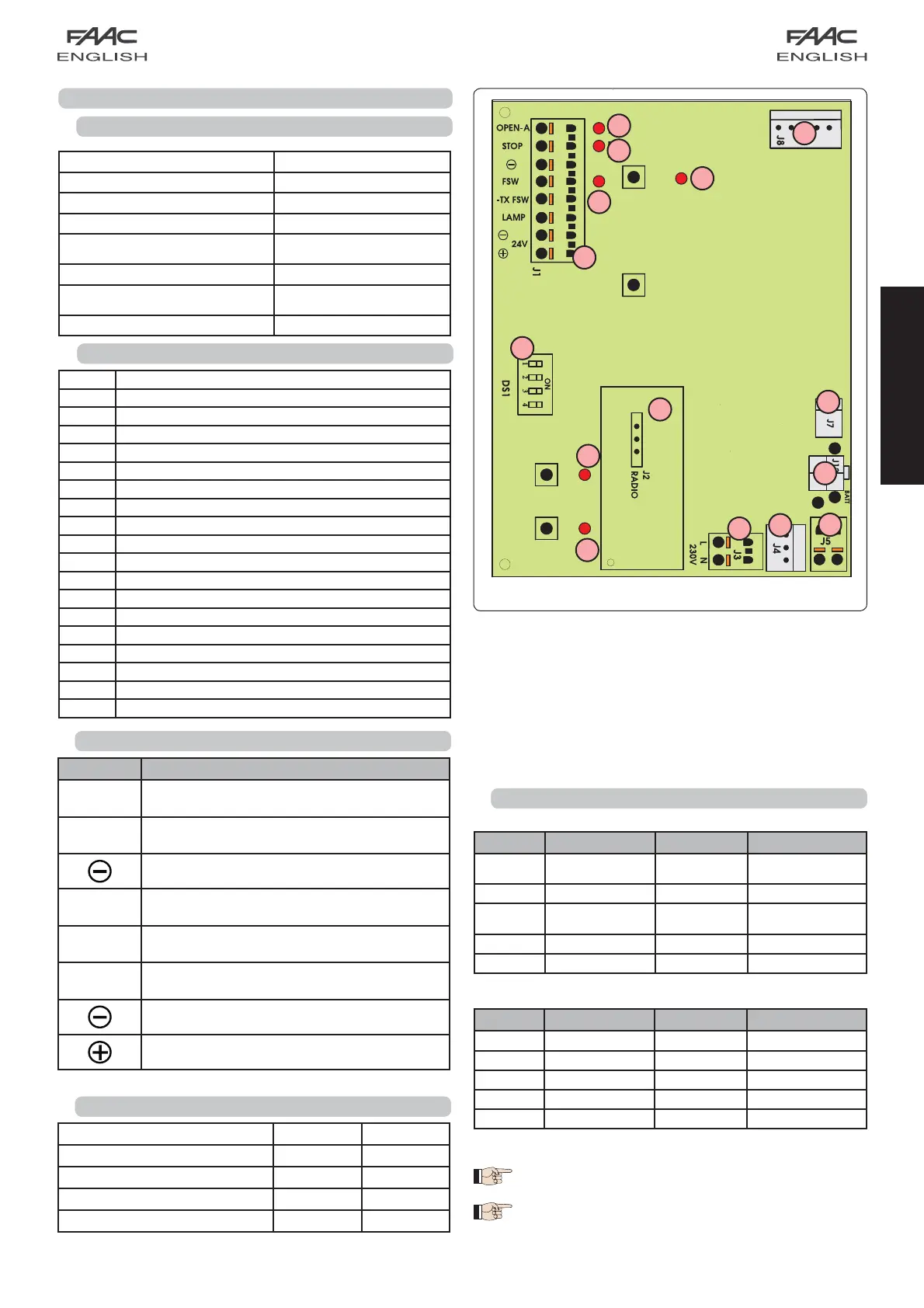
10
J7
J8
J4
J1
J2
J5
J3
J12
DS1
SET UP
OPEN
LD6
LD5
LD4
OPEN BOPEN A
LD3
LD2
LD1
ENGLISH
8.3 Terminal-boards and connectors
8.2 E600 board components
8 E600 CONTROL BOARD
8.1 Technical specifications
Fig. 25
8.4 DS1 Programming dip-switches
8.5 Operating logics
Logic A (automatic)
Logic E (semi-automatic)
(1) Prevents closing if pulse is maintained.
(2) Prevents closing and/or opening if pulse is
maintained.
Description Connected device
OPEN A
Command device with N.O. contact
(see chap. OPERATING LOGICS)
STOP
Device with N.C. contact which stops the
automated system
Negative for OPEN A and STOP devices
FSW
Closing safety device with N.C. contact (see
chap. OPERATING LOGICS)
LAMP
OPEN COLLECTOR 24 Vdc 100 mA. output for
flashing lamp
-TX FSW
Negative for powering safety accessories (FAIL
SAFE function)
Negative for powering accessories
+24 Vdc for powering accessories
No. Function OFF ON
1 Fail Safe Enabled
Not enabled
2 Anti-crushing sensitivity Low High
3 Not used / /
4 Carriage speed High Low
Status Open (pulse) Stop Fsw
CLOSED
Opens and closes
after pause time
No effect (2) No effect
OPENING No effect Locks (2) No effect (1)
OPEN IN
PAU SE
Resumes counting of
pause time (1)
Locks (1)
Resumes counting of
pause time (1)
CLOSING Reverses motion Locks (2) Reverses motion
LOCKED Closes No effect (2) No effect (1)
Status Open (pulse) Stop Fsw
CLOSED Opens No effect (2) No effect
OPENING Locks Locks (2) No effect (1)
OPEN Closes No effect (2) No effect (1)
CLOSING Reverses motion Locks (2) Reverses motion
LOCKED Closes No effect (2) No effect (1)
Supply voltage (V ~ / Hz.)
230 / 50
Power supply to accessories (Vdc)
24
Accessories max. load (mA.)
200
Operating ambient temperature (°C)
-20 / +55
Quick-fit connector
for receiver boards XF433 /
XF868 and battery module
Operating logics
Automatic / Semiautomatic
Terminal-board connections
Open/Stop/Safety devices/Fail-
safe/Flashing lamp 24 Vdc
Courtesy light timer (min.)
2
J1 Low voltage inputs/accessories terminal board
J2
Quick-fit connector for receivers XF433 or XF868
J3 230V power supply input terminal board
J4 Connector for transformer primary winding
J5 Courtesy light terminal-board
J7 Connector for transformer secondary winding
J8 Motor output connector
J12 Battery module connector
OPEN A Radio signal programming push-button
OPEN B Radio signal programming push-button
OPEN OPEN push-button
SETUP SET-UP push-button
DS1 Programming dip-switch
LD1 Signalling LED: OPEN input
LD2 Signalling LED: STOP input
LD3 Signalling LED: FSW input
LD4 Signalling LED: SET UP cycle
LD5
LED signalling memory-storage: radio channel OPEN A
LD6
LED signalling memory-storage: radio channel OPEN B
Fail Safe
If activated, it enables the photocell operating test before every
movement.
Operating logics
For doors with an irregular movement, it reduces the sensitivity of
the anti-crushing device to prevent unwanted action by it.