5
Fig. 2
ENGLISH
7 INSTALLATION OF BUS ACCESSORIES
This board is supplied with a BUS circuit enabling easy con-
nection of a high number of BUS accessories (e.g. up to 16
photocells pairs), appropriately programmed, using only two
cable without polarity.
Below we describe the addressing and memory storage of
the BUS photocells.
For other future accessories, refer to the specific instructions.
7.1 ADDRESSING THE BUS PHOTOCELLS
Important: the same address must be given to
both transmitter and receiver.
Make sure that there are no two or more
photocells pairs with the same address.
If no BUS accessory is used, leave the BUS con-
nector free (J10 - fig. 1).
A maximum of 16 BUS photocell pairs can be connected to
the board.
The photocells are split into groups:
Opening photocells: max 6
Closing photocells: max 7
Opening /Closing photocells: max 2
Photocell used as an OPEN pulse: max 1
Dip1 Dip2 Dip3 Dip4 Ref. Type
OFF OFF OFF OFF
B -C OPENING
OFF OFF OFF ON
OFF OFF ON OFF
OFF OFF ON ON
OFF ON ON OFF
OFF ON ON ON
ON OFF OFF OFF
D CLOSING
ON OFF OFF ON
ON OFF ON OFF
ON OFF ON ON
ON ON OFF OFF
ON ON OFF ON
ON ON ON OFF
OFF ON OFF OFF
A
OPENING and
CLOSING
OFF ON OFF ON
ON ON ON ON / OPEN PULSE
Tab. 3 - Addressing of BUS Photocells
Table 3 shows the programming operations of the dip-switch
inside the transmitter and of the BUS Photocells receiver.
If the A Logic was selected, the board begins to count the
pause time (max 10 min) and, after the required time has
elapsed, give an OPENING pulse to continue the proce-
dure. Otherwise, if you have selected the EP logic, give an
OPEN pulse to continue the procedure.
Leaf 2 (if present) starts the closing movement an the board
begins to count the delay of the leaf at closing.
After the required time has elapsed, give an OPEN pulse
to make leaf 1 start the closing movement. If leaf 2 is not
present, the pulse given in point 9 directly makes leaf 1
close.
Leaves 1 and 2 (if present) stop when they reach the closing
mechanical stop.
Wait for LEDs LD4 and LD5 to go OFF, which means that the
SETUP procedure has finished.
When the SETUP procedure has been started,
if the leaves at point 4 and 5 open instead of
closing, the motor power supply cables must
be changed over.
When using the MANUAL SETUP, the slow-down
spaces, and leaf delays at opening are preset
by the board and cannot be modified. However,
delay at leaf closing and pause time can be
programmed during learning.
10.
11.
12.
13.
14.
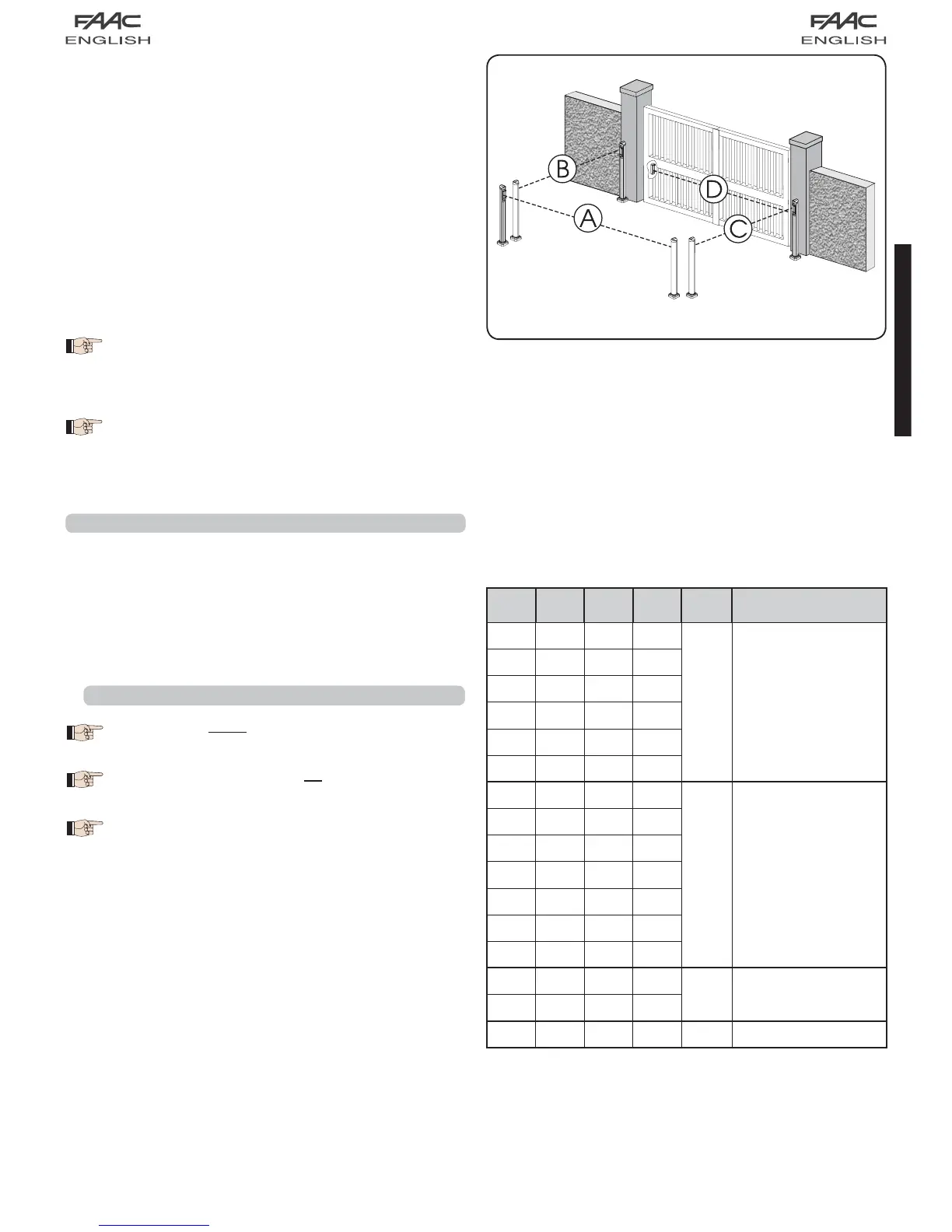
Fig. 2 shows a 2-swing leaf automated system indicating the
coverage beams of the photocells:
A: Photocells with OPENING and CLOSING action.
B: Photocells with OPENING action
C: Photocells with OPENING action
D: Photocells with CLOSING action