3
ENGLISH
3 TECHNICAL SPECIFICATIONS
Power supply voltage
230Vac (+6% -10%) - 50Hz
Absorbed power
20W
Motor max. load
150W x 2
Accessories max. current
(+24V)
100 mA
BUS Accessories max.current
400 mA
Operating ambient tempera-
ture
-20°C - +55°C
Fuses
F1 = self-resetting; F2 = T2A-
250V
Function logics
EP, A
Work time (time-out)
1 minute (fixed)
Pause time
Varies according to learning
(max. 10 min.)
Terminal board inputs
Open A, Open B, Stop, BUS
(I/O)
Connector inputs
Power supply, battery
module XF 433 or XF 868
Terminal board outputs
Motors, flashing lamp, power
supply to accessories,
electric lock, service light
contact (90 sec fixed)
Programmable functions
Logic (A, EP), Speed (depen-
ding on the motorization)
Learning functions
Pause time, leaf 2 delay at
closing
Integrated radio channels
type
DS, SLH (max 250 channels)
LC (max 250 channels - FOR
SOME MARKETS ONLY)
J1 POWER SUPPLY connector
J2
SERVICE LIGHT command terminal-board
J3 FLASHING LAMP terminal-board
J4 ELECTRIC LOCK terminal-board
J5 COMMANDS terminal-board
J7 MOTOR 1 terminal-board
J8 MOTOR 2 terminal-board
J9 Rapid connection for XF MODULE
J10 BUS terminal-board
J11 BATTERY connector
SW1 SET UP push-button
SW2 SPEED push-button
SW3 LOGIC push-button
DS1 Programming Dip-switch
F1 Accessories protective fuse
F2 Fuses protecting transformers and motors
LED Signalling LEDs
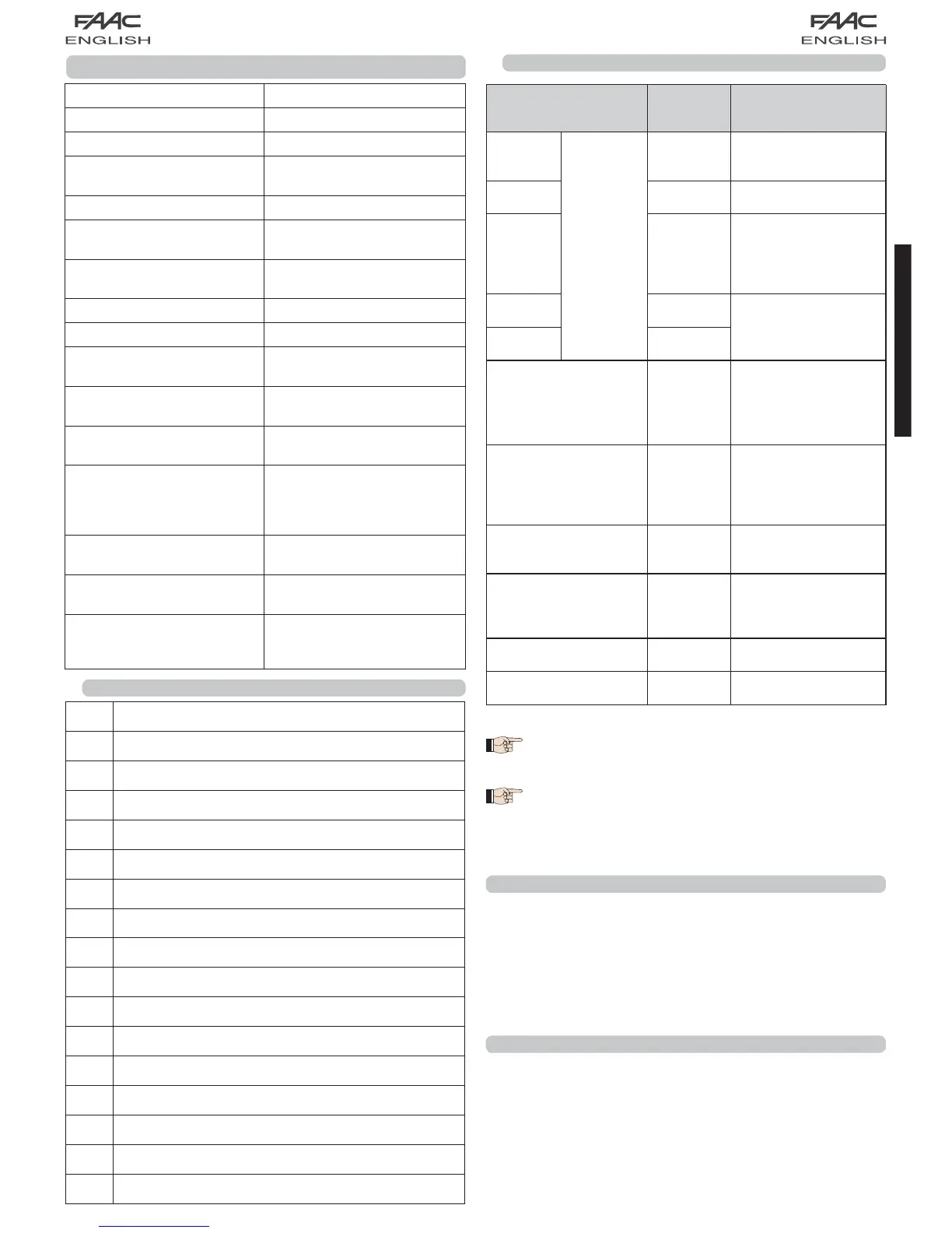
3.1 DESCRIPTION OF COMPONENTS
Terminal and/or
terminal-board
Description Device connected
1
J5
+24V
Power supply for
accessories
2 GND Negative
system to shut down
4 OPEN B
Device with N.O
contact (see chap.
FUNCTION LOGICS)
5 OPEN A
J10
RED terminal
BUS
Safety devices with
BUS technology
J2
GREY terminal
SERVICE
LIGHT
Service Light control
output (connect a
relay coil at 24Vdc-
100mA max)
J3
ORANGE terminal
LAMP
Flashing lamp 24Vdc
- 15W
J4
BLUE terminal
LOCK
Electric lock 12Vac or
24 Vdc (to be installed
on leaf 1)
J7 MOT1 Motor 1 (leaf 1)
J8 MOT2 Motor 2 (leaf 2)
3.2 DESCRIPTION OF TERMINAL-BOARDS
4 PROGRAMMING THE LOGIC
The function logic can be selected at any time by pressing
push-button SW3.
The selected logic is then displayed on LED LD7:
LED on = AUTOMATIC logic (A)
LED off = SEMIAUTOMATIC STEPPED logic (EP)
5 PROGRAMMING THE SPEED
The function logic can be adjusted at any time by pressing
push-button SW2.
The selected logic is then displayed on LED LD8:
LED on = HIGH speed
LED off = LOW speed
Leaf 1 means the leaf which opens first during
the opening operation.
The service light control is active during the
entire gate opening or closing movement and
for the successive 90 seconds.