E721 3 532014 - Rev.E
ENGLISH
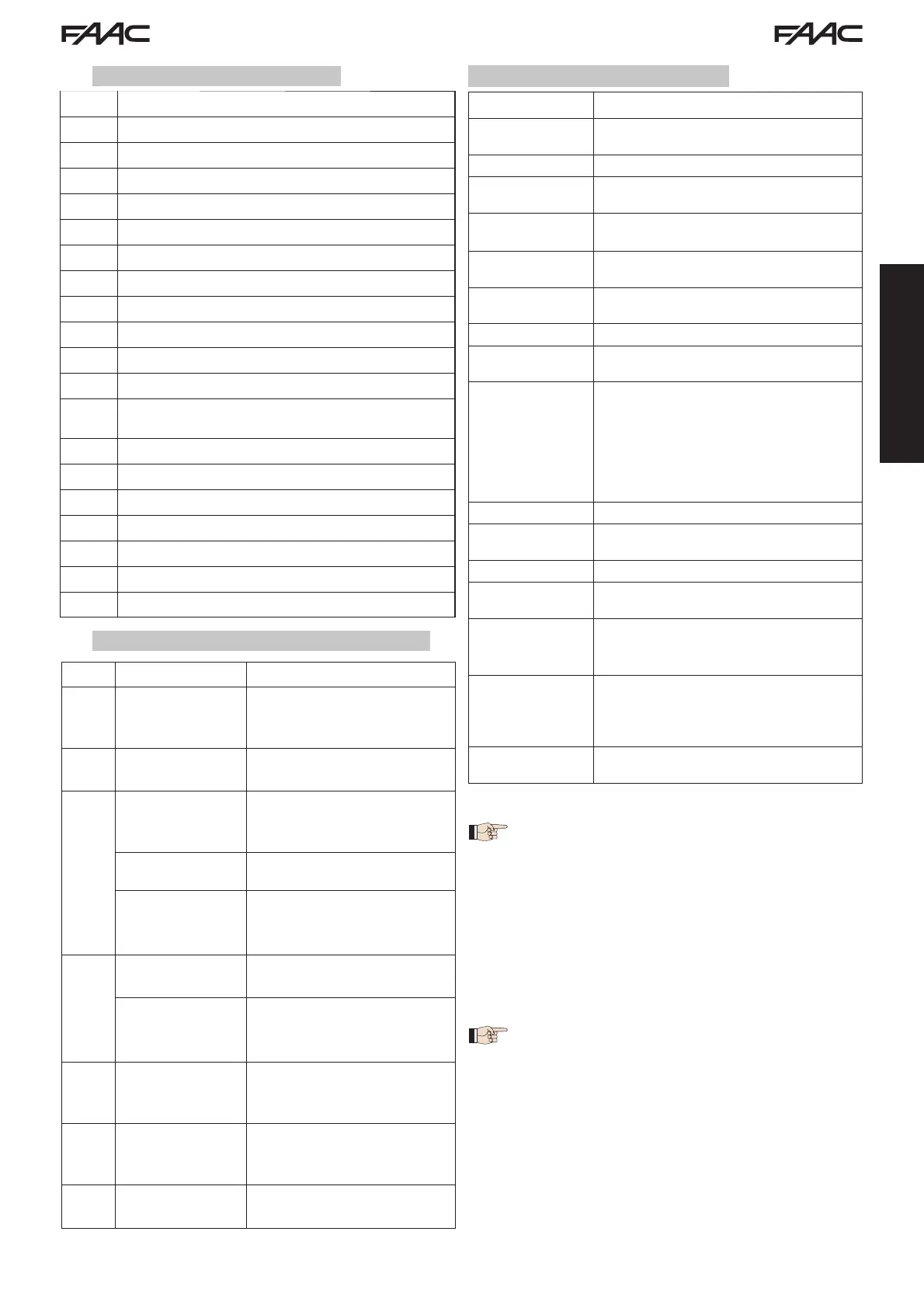
LCD SIGNALLING AND PROGRAMMING DISPLAY
SW1 PROGRAMMING PUSH-BUTTON "F".
SW2 PROGRAMMING PUSH-BUTTON "-".
SW3 PROGRAMMING PUSH-BUTTON "+".
SW4 “SETUP” PUSH-BUTTON
LEDs INPUTS STATUS CONTROL LED
J1 MAIN POWER SUPPLY CONNECTOR
J2 TRANSFORMER PRIMARY WINDING CONNECTOR
J3 TRANSFORMER SECONDARY WINDING CONNECTOR
J4 EMERGENCY BATTERY CONNECTOR (ACCESSORY)
J5 MOTOR CONNECTOR
J6 FLASHING LAMP CONNECTOR (24 V= - 15W)
J9
MOTOR LOCK AND
MOTOR RELEASE
CONTACT
CONNECTOR
J10 OUT OUTPUT CONNECTOR
J11 USB CONNECTOR FOR PC CONNECTION
J12 BUS-2EASY DEVICE CONNECTION CONNECTOR
J13 INPUT CONNECTOR IN CONNECTOR BLOCK
J14 RADIO RECEIVER MODULE CONNECTOR FOR OMNIDEC
LCD1 SIGNALLING AND PROGRAMMING DISPLAY
F1 PROTECTION FUSE
INPUT No DESCRIPTION
1 OPEN A Device with N.O. contact
that causes total opening
of the gate
2-6 GND Accessory power
supply negative
3
(1)
OPEN B
(DEFAULT)
Device with N.O. contact
that causes partial opening
of the gate
CLOSE
Device with
N.O.
contact
that closes the gate
SAFE Device with N.C. contact
that causes the immediate
and complete reversal of
the gate
4
(1)
STOP
(DEFAULT)
Device with N.C. contact
that halts the gate
SAFE Device with N.C. contact
that causes the immediate
and complete reversal of
the gate
5 FSW OP Device with N.C contact
that reverses the motion
during gate opening
7 FSW CL Device with N.C contact
that reverses the motion
during gate closing
8 +24 V= Accessory power supply
positive
Power supply
230 V VERSION : 230 V~ 50 Hz
115V VERSION : 115 V~ 60 Hz
Power consumption
from mains stand-by
10 W
Motor max. load 10A
Accessory
power supply
24 V=
Accessory
max. current
24 V= max. 500 mA
BUS-2EASY max. 500 mA
Environmental
temperature
(-20 - +55) °C
Flashing lamp
load
24 V= - 15 W
Output load 24 V= - 100 mA (2)
Protection
fuses
F1 = T1A - 250V~
Function
logics
Semiautomatic, Semiautomatic “step“,
Automatic, Automatic “step”, Auto-
matic with timer function, Automatic
Safety devices, Automatic Safety devices
“step“, Automatic with reverse on pause,
Semiautomatic “b”, Mixed logic “bC”,
Dead-man.
Work time Programmable (from 0 to 10 min.)
Pause time
OPEN A / OPEN B
Programmable (from 0 to 10 min.)
Motor power Adjustable over 50 levels
Opening-closing
motor speed
Adjustable over 10 levels
Connector Inputs/
Outputs
Power supply, Battery, Motor, Module
XF433/868,
Motor lock electric release bat-
teries, Motor Lock,
USB
Inputs/Outputs in
terminal block
BUS-2EASY, OPEN A, OPEN B/CLOSE/SAFE,
STOP/SAFE, GND, Opening and closing
photocells, +24 V=, Mains power supply,
Flasher, Electric release
motor lock, OUT
Programming
1
st
and 2
nd
level with 3 keys (+, -, F) and
display.
3 TECHNICAL SPECIFICATIONS
2.1 COMPONENT DESCRIPTION
2.2 DESCRIPTION OF TERMINAL BLOCK J13
(2) The output load must be considered
as already included in the max. current
available for the accessories
(1) The uses of inputs 3 and 4 can be set by
configuring the corresponding parameters
at programming level 2 (parameters
Ob
and
SP
). For the exact description on how
to operate the automated system with the
chosen logics, please refer to the tables
featured at the end of this manual (Par.
10 - OPERATION LOGICS. As for the wiring
required using these SAFE configured
inputs, please refer to the diagrams shown
in Fig.13 and Fig. 14
 Loading...