E721 4 532014 - Rev.E
C720 C721
E721 E721
Fig. 2
Fig. 4
/ SAFE
=
=
/ SAFE
Fig. 3
230 V
~
115 V
~
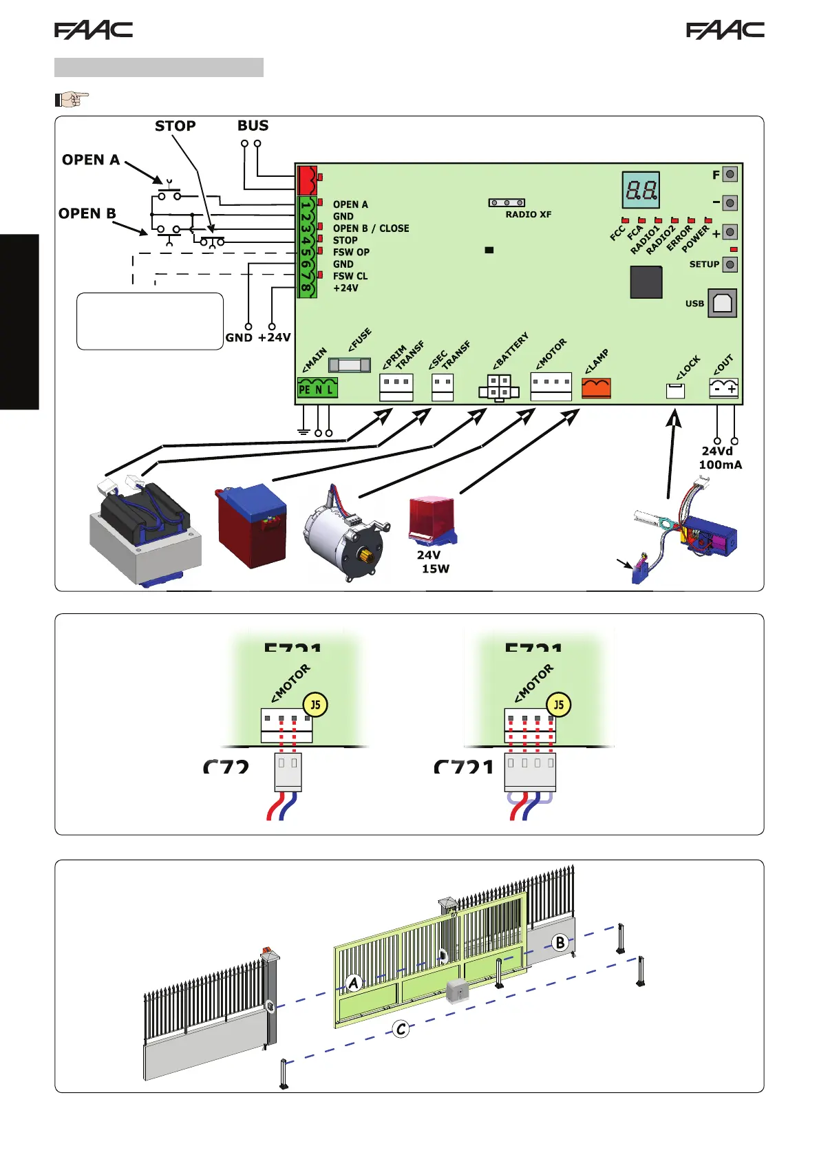
ENGLISH
A: Photocells that operate during CLOSING
B: Photocells that operate during OPENING
C: Photocells that operate during OPENING and CLOSING
MOTOR RELEASE
CONTACT
The microswitch is con-
nected to the lever to
unlock the motor. When the
microswitch is activated
the display shows the
status--.
4 ELECTRIC CONNECTIONS
To connect the photocells
and safety devices, con-
sult paragraph 4.2
The wiring shown in Fig. 2 refers to the inputs of the board with DEFAULT configuration.