27
Measuring Engine Tach (Rotation Speed)
1. Connect the black test lead to the "COM" terminal and the red test lead to the " " terminal. (Note: The polarity of
the red lead is positive "
+". )
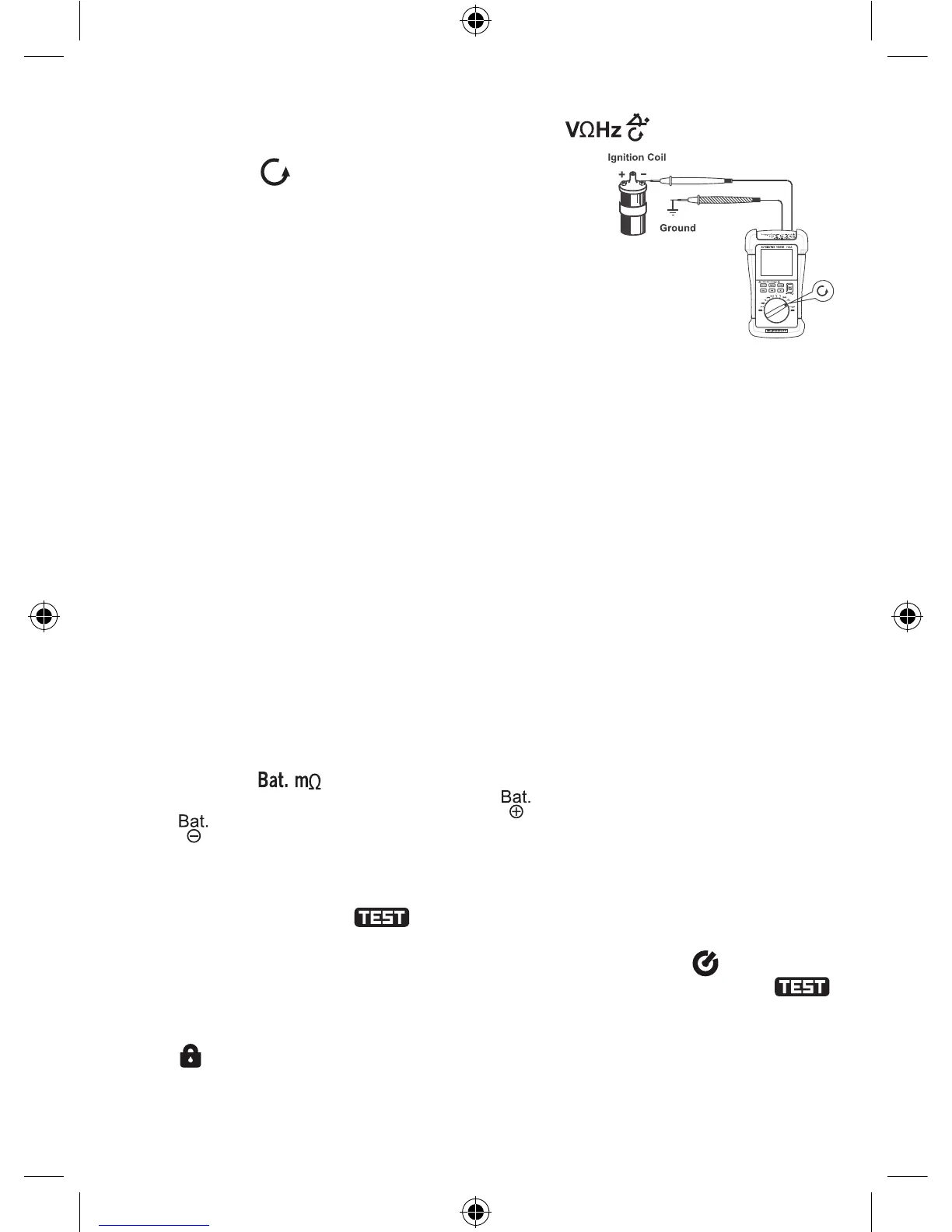
2. Set the range switch to position.
3. Press the "SELECT" button until the number of cylinders of the engine to be tested
appears.
4. Connect the black test lead to ground or the negative terminal of the battery and the
red test lead to the lowvoltage terminal of the distributor or the negative terminal of the
ignition coil.
5. Start the engine and read the reading on the display.
Note:
1. The input voltage must be between 3V peak and 50V peak. If the voltage is too low, it
will be impossible to make measurement.
2.Themeter’smeasurementrangeisfrom250RPMto40kRPM.Iftheengine’sactualrotationspeedisoutofthisrange,measurement
may be incorrect. To measure a rotation speed which is out of this range, you can measure the ignition frequency, and then determine
the rotation speed by using the formula: N= 120F/C
In this formula, Nisrotationspeed(unit:RPM),F is ignition frequency (unit:Hz), C is the number of cylinders.
3. The polarity of the input voltage must be correct, otherwise it will be impossible to make measurement.
Measuring Vehicle’s Battery Internal Resistance
Note:
Useonlythe4-wiremeasurementmethodtoperformtheinternalresistancemeasurement.Makesurethattheconnectionsarecorrect.
Caution:
1. To avoid damage to the meter, don’t use the meter to measure battery’s internal resistance if the battery’s voltage exceeds 36V.
2. To avoid damage to the battery, don’t short the battery’s terminals while making connections.
3. To avoid error caused by test lead, make sure that the resistance of each test lead (with clip) is less than 5Ω . (Two test leads share
a clip.)
4. Before measurement, check the meter’s fuse.
Measurement Procedure:
1. Set the range switch to position.
2. See Figure 8, insert the plugs of the two red test leads into the two " " terminals and the plugs of the two black test leads into
the two " " terminals.
3. Remove the oxide layer on the surface of the battery terminals. Clip the red clip to the battery’s positive terminal, and clip the
blackcliptothebattery’snegativeterminal(Figure8).Note:Foraccuratemeasurement,thetwojawsofeachclipmustnottouch
each other directly (Figure 8 ).
4. Press the "TEST" button, the indicator " " appears on the display indicating that the internal resistance measurement is
being performed. Read the reading on the display. If the internal resistance is more than 4000mΩ , the built-in buzzer will sound.
5. To stop the measurement : In Step 4, if you press the "TEST" button momentarily, the indicator " " will appear on the
display indicating that the internal resistance measurement is in Fixed Time Test mode. About 60 seconds later, the indicator " "
will disappear and the internal resistance measurement will stop automatically.
In Step 4, if you press and hold down the "TEST" button for more than 2 seconds to start the internal resistance measurement, the
indicator " " will appear on the display indicating that you can perform the measurement as long as you like. The measurement
will not stop until you press the "TEST" button again.
After internal resistance measurement starts, the built-in buzzer sounds a beep about every 10 seconds to remind you that the
measurement is being performed.
figure 7