®
10
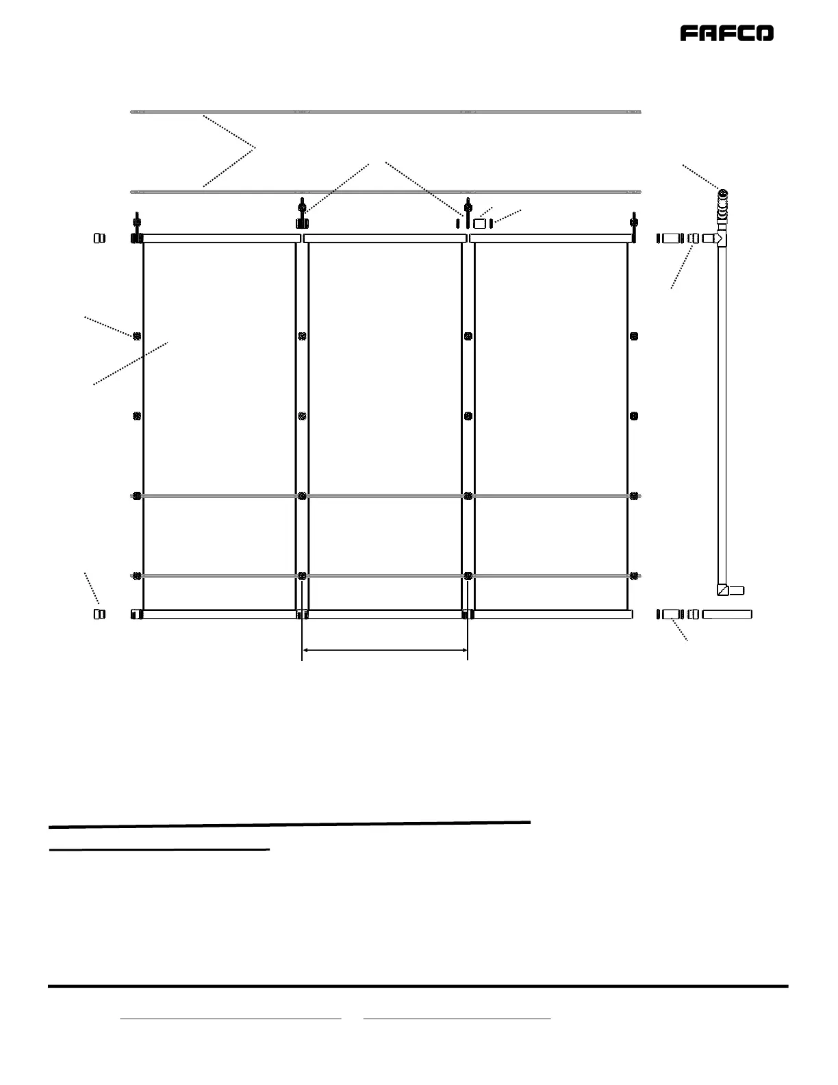
Refer to the Array Components List on the previous pages for further details about the array components in the above figure
*Header Straps must be installed directly perpendicular to header and fix-mounted panel must be wrapped twice, with mounting cleat roughly 2” away from header
** Number of Body Straps determined by local wind load requirements
System Overview Cont’d
Figure 4 | Typical SunSaver
®
Array Layout Components
The typical SunSaver
®
solar pool system consists of a combination of FAFCO
®
-sourced parts and standard equipment. The above figure and the component list below
depicts common Array Layout Components and shows the proper placement of all components.
Legend for Figure 4
Array Layout Components
SunSaver
®
Collector (4ft wide)
SunSaver
®
Collector (2ft wide) (not shown)
Vacuum Relief Valve
End Cap
Pipe Adapter
Base
Cap
1
2
3
4
5
6
7
Hose Clamp
3-1/2” Hose Coupler
5” Hose Coupler
Header Straps*
Body Straps**
Substrate (not shown)
8
9
10
11
12
13
1
3
4
5
6&7
8
9
10
11*
12**
51-1/2” ± 1/4”
Centered Between Collector Gaps
at Operang Temperature