EasyManuals Logo

Fagor DDS AXD/SPD 2.50 User Manual

Fagor DDS AXD/SPD 2.50
406 pages
To Next Page IconTo Next Page
To Previous Page IconTo Previous Page
Page #351 background imageLoading...
Page #351 background image
Connection diagrams
10.
Ref.1912
· 351 ·
DDS
HARDWARE
Diagram of the maneuver
F. H10/2 4
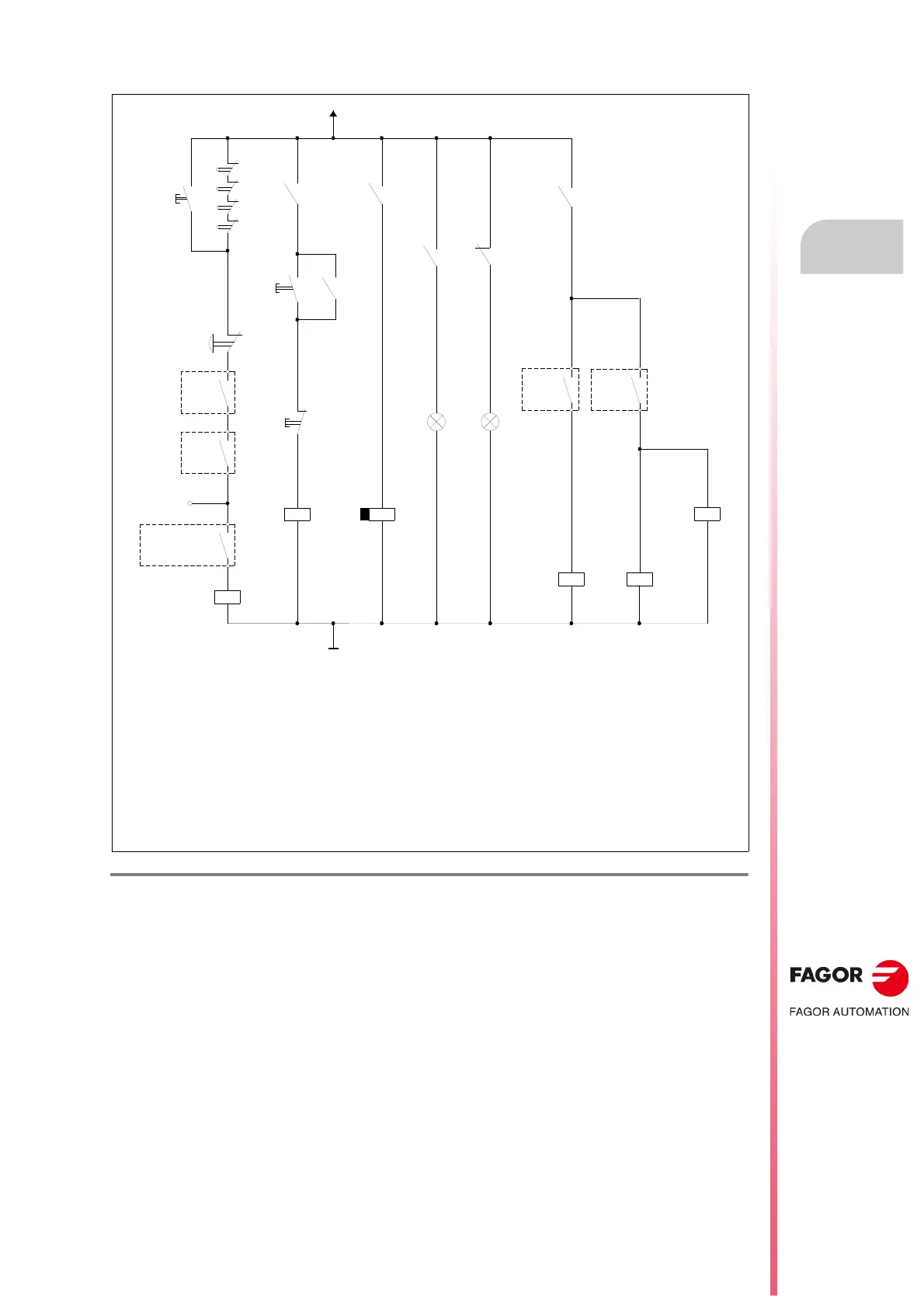
Compact DDS system. ACD/SCD, SERCOS. Diagram of the maneuver.
Important.
The relay - KA3 uses delayed deactivation (t seconds) maintaining the DRIVE ENABLE control signal active for
a few seconds to maintain motor torque while the vertical axis holding brake is enabled.
See parameter GP9 in the “man_dds_soft.pdf” manual.
Note.
CNC EMERG. will always be assigned to I1/O1 of the PLC with an 8055/55i CNC. With an 8070 CNC, it may be
assigned to any I/O of the PLC. The contacts associated with relays - KA3, - KA4 and - KA6 are shown in fig.
F.
H10/22
and the contactor - KM1 in fig.
F. H10/23
.
EMERG.
STOP
DR.X
OK
DR.Z
OK
I1 PLC
CNC EMERG.
O1 PLC
-KA1
EMERGENCY LINE
GND
ON OFF
TO SPEED ENABLES
-KA4
-KA6
BRAKE
CONTROL
-BRK
CNC
ENABLE
X
CNC
ENABLE
Z
KM1
KA3
KM1
+24 V DC
X+
X-
Z+
Z-
KA1
ON
KM1
OFF
-KM1
DELAY OFF
-KA3
DRIVE
ENABLES
ON
Green
OFF
Red
t (s)
KA3

Table of Contents

Questions and Answers:

Question and Answer IconNeed help?

Do you have a question about the Fagor DDS AXD/SPD 2.50 and is the answer not in the manual?

Fagor DDS AXD/SPD 2.50 Specifications

General IconGeneral
BrandFagor
ModelDDS AXD/SPD 2.50
CategoryDC Drives
LanguageEnglish

Related product manuals