40
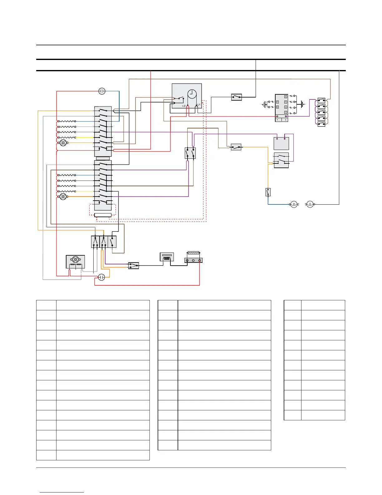
10. Circuit Diagram
6
P6
5 P5
4
P4
7 P7
8 P8
2
P2
1
P1
3 P3
a
b
e
f
c
d
1
2
v
32
31
21
22
24
14
12
12
1
2
P2
P1
A1
A2/B1
B2
6
P6
5 P5
4
P4
7 P7
8 P8
2
P2
1
P1
3 P3
11
or
gy
b
gy
w
y
or
r
br
w
b
gy
w
y
or
r
r
r
br
br
b
v
bk
b
r
bk
v
br
v
bk
r
r
or
w
bk
brw or vgy
g ywr
r
or
or
v
r
v
br
br
v
br
or
or
or
v
v
v
b
w
w
rv
r
br
bk
bk
r
bk bk
bk
wb
bk bk
br
v
br
br
br
N
A
A1
A2
B1
B2
K
G
H3
H2H2
J
M
O
P
D
Q2
R
I
Q1
H1
Q3
C1
C2
C3
C4
C5
F1
F2
F3
F4
F5
Code Description
A1 MF oven master switch
A2 MF oven drone switch
B1 Oven thermostat
B2 Oven front switch
C1 Right-hand oven base element
C2 Right-hand oven top outer element
C3 Right-hand oven top inner element
C4 Right-hand oven fan element
C5 Right-hand oven fan
D Cooling fan (2 speed)
F1 Left-hand oven base element
F2 Left-hand oven top outer element
F3 Left-hand oven top inner element
F4 Left-hand oven fan element
F5 Left-hand oven fan
Code Colour
bl Blue
br Brown
bk Black
or Orange
r Red
v Violet
w White
y Yellow
g/y Green/yellow
gr Grey
r(f) Red (ag)
Code Description
G Oven protect thermostat
H1 Oven neon
H2 Oven light
H3 Oven light switch
I Door lock neon
J Ignition spark generator
K Oven divider switch (In)
M Ignition switches
O Cooling fan fail cut-out
P Pyrolytic thermostat
Q1 Lock cam switch
Q2 Lock motor
Q3 Lock motor resistor
R Clock / oven timer