35
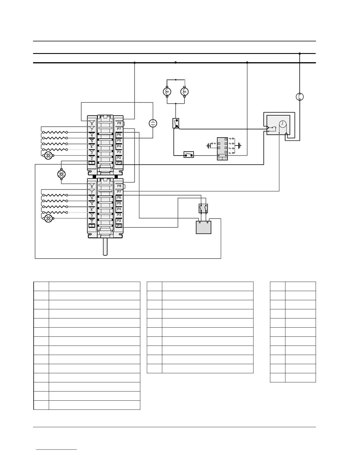
10. Circuit Diagram
a
b
e
f
c
d
1
2
A
N
N
A
1 2
b
gy
w
y
o
b
gy
w
y
o
v
v
r (f)
r
r
r
r
br
r
r
r
v
br
b
bk
v
v
vbr
br
br
r
w
bb
rbr
r
bk
bk
r
bk
Black boots
Clear boots
r (f)
r (f)
r (f)
bk
bk
bk
bk
bkr
bk
bk
bk
b
D2
C4
G2
K
A2
B
D1
C3
G1
D5
E
C2
G2
D4
L
C5
C1
J
D3
I
H
F
A1
Key
The connections shown in the circuit diagram are for single-phase. The ratings are for 230 V 50 Hz.
Code Colour
b Blue
br Brown
bk Black
or Orange
r Red
v Violet
w White
y Yellow
g/y Green/yellow
gr Grey
Code Description
A1 Multi-function oven master switch
A2 Multi-function oven drone switch
B Multi-function oven thermostat
C1 Right-hand base element
C2 Right-hand top outer element
C3 Right-hand top inner element
C4 Right-hand fan element
C5 Right-hand fan
D1 Left-hand base element
D2 Left-hand top outer element
D3 Left-hand top inner element
D4 Left-hand fan element
D5 Left-hand fan
Code Description
E Cooling fan
F Clock
G1 Oven light switch
G2 Oven light
H Tap switches
I Spark generator
J Oven neon
K Thermal cut-out
L Divider switch