OM48017A
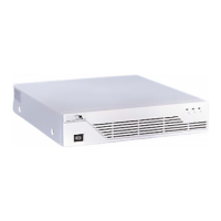
AC - A green L.E.D. that is illuminated when
both the power On/Off is “ON” and there is
utility power present at the input of the input of
the SSG500. The FILTERED load outlets, if
available, will be active if this L.E.D. is “ON”
INV - A green L.E.D. that illuminates when the
SSG500’s Inverter is operating and powering
the UPS load outlets.
ALM - A red L.E.D. that illuminates if the
inverter malfunctions and is no longer
supplying power to the UPS load outlets.
During this condition, UPS load outlets will be
powered by filtered utility bypass power.
Power ON~OFF Switch The system power
switch that allows utility power to activate the
Inverter and Battery circuits.
SIGNAL - A DB-9 subminiature female
connector provided for sophisticated computer
monitoring systems..
UPS OUTPUT Continuous power is provided
at the UPS output receptacles.
Identification Label - The SSG500’s model
and serial numbers are located here. Always
refer to this information during correspondence
with the factory.
INPUT -. The SSG500 comes with removable
line cord.
INPUT FUSE - This is the input protection line
fuse to the SSG500. It also provides protection
to the critical load if on the emergency bypass
line.
FUSE - This is the output protection fuse to the
load.
COOLING FAN - This device forces cool air
into the SSG500 so it can maintain longer and
more efficient operation.

 Loading...