Do you have a question about the Falcon SG1KRM-2TU and is the answer not in the manual?
Explains the benefits of true regenerative online UPS for maximum system availability and protection.
Highlights the state-of-the-art input power factor correction for efficient building wiring.
Details the advanced microprocessor technology for UPS control and management, including software support.
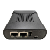
Describes the optional SNMP/HTTP agent for remote monitoring and management over Ethernet.
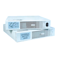
Covers the support for optional external battery/charger packs for extended runtime.
Explains the option to configure the UPS as an international frequency converter.
Summarizes crucial safety warnings, cautions, and important guidelines for UPS installation and operation.
Provides a detailed explanation of the true regenerative online design for superior power protection.
Details the benefits of input power factor correction for system efficiency and reduced current demand.
Explains the microprocessor technology for UPS management and its software compatibility.
Describes the capabilities of the optional SNMP/HTTP agent for network monitoring.
Covers the flexibility of adding external battery packs for longer backup times.
Details the frequency conversion capability for global power applications.
Lists the items to verify are included in the UPS and battery module shipping cartons.
Emphasizes critical instructions for mounting UPS and battery banks securely in racks.
Provides steps for assembling and installing rackmount handles and brackets.
Details how to install a suitable shelf and secure the UPS and battery banks within the rack.
Explains the functions of the three switches located on the UPS rear panel.
Guides users on setting the UPS output voltage using the dip switches on the rear panel.
Instructs on connecting the UPS power cord and output cords for protected equipment.
Details the wiring process for connecting primary and extended battery modules.
Explains how to connect for unattended shutdown and monitoring via UPS/Computer cable.
Ensures proper ventilation and final connection steps before powering on the UPS.
Guides on powering up the UPS and the initial 24-hour battery charging period.
Details the correct procedure for turning off the UPS unit safely.
Provides instructions for installing the optional slide mounting kit for rackmount UPS.
Important note regarding the correct length of screws to use for slide mounting.
Explains the load level indicator LEDs and their meaning based on output load percentage.
Describes the battery level indicator LEDs for charged status and low battery warnings.
Details the line/site wiring fault LED, including normal operation and fault conditions.
Explains the battery mode indicator LED which lights up when the unit operates from battery.
Indicates when the UPS bypass is active and potential internal failures.
Shows when the UPS inverter is operating and powering the connected load.
Indicates when the UPS is in Green Mode, saving power by reducing inverter operation.
Lights up when the connected load approaches the UPS peak current rating.
Illuminates during various fault conditions like high/low voltage or over-temperature.
Details the operation modes of the ON/OFF button for starting, bypassing, and shutting down the UPS.
Explains the functions of the TEST button for resetting Green Mode, self-diagnostics, and alarm muting.
Describes normal or correctable operational alarms, such as battery mode or overload.
Details abnormal operation alarms like output voltage/frequency errors or over-temperature.
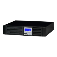
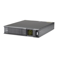
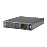
Provides an overview of the control and display panel on the front of all UPS models.
Details the rear panel components for the SG1KRM-1TU model, including ports and connectors.
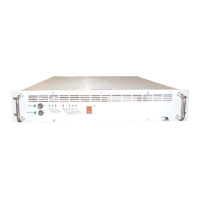
Details the rear panel components for the SG1KRM-2TU model, including ports and connectors.
Details the rear panel layout for the SG2KRM-1TU and SG3KRM-1TU models.
Details the rear panel layout for the SG2KRM-2TU and SG3KRM-2TU models.
Describes the standard RS-232 interface port located on the UPS rear panel.
Lists the supported communication protocols for UPS monitoring and management.
Details the pinout assignment for the DB-9 female connector used for RS-232 communication.
Details pin and jumper assignments for the UA88374 relay option board (no on-bypass signal).
Details pin and jumper assignments for the UA88376 relay option board (with on-bypass signal).
Provides pin assignment details for the UA88373 opto-coupler option board (no-bypass signal).
Illustrates the internal circuitry of the opto-coupler interface board.
Provides guidance on cleaning and maintaining the UPS for optimal performance.
Explains the relationship between ambient temperature and battery lifespan for the UPS.
Details when and how to replace the UPS batteries, including safety warnings.
Provides instructions for proper storage of the UPS and its batteries to prevent damage.
Outlines FCC regulations compliance and measures to correct radio interference.
Lists Falcon Electric's contact details for technical assistance and service.
Explains how to request technical information or support via email or telephone.
Directs users to the Falcon website for product data sheets and manuals.
Covers the warranty period, covered repairs, and specific exclusions from the warranty.
Details limitations on liability for incidental, consequential, or commercial losses.
Explains warranty transferability and the commencement date of item coverage.