19
Section 2: Setup
NOTE: The bus bar caps and contacts are
a matched set. If the caps are completely
removed from the contacts, match the
number stamped on the inside of each
cap to the number stamped on the end of
the contact.
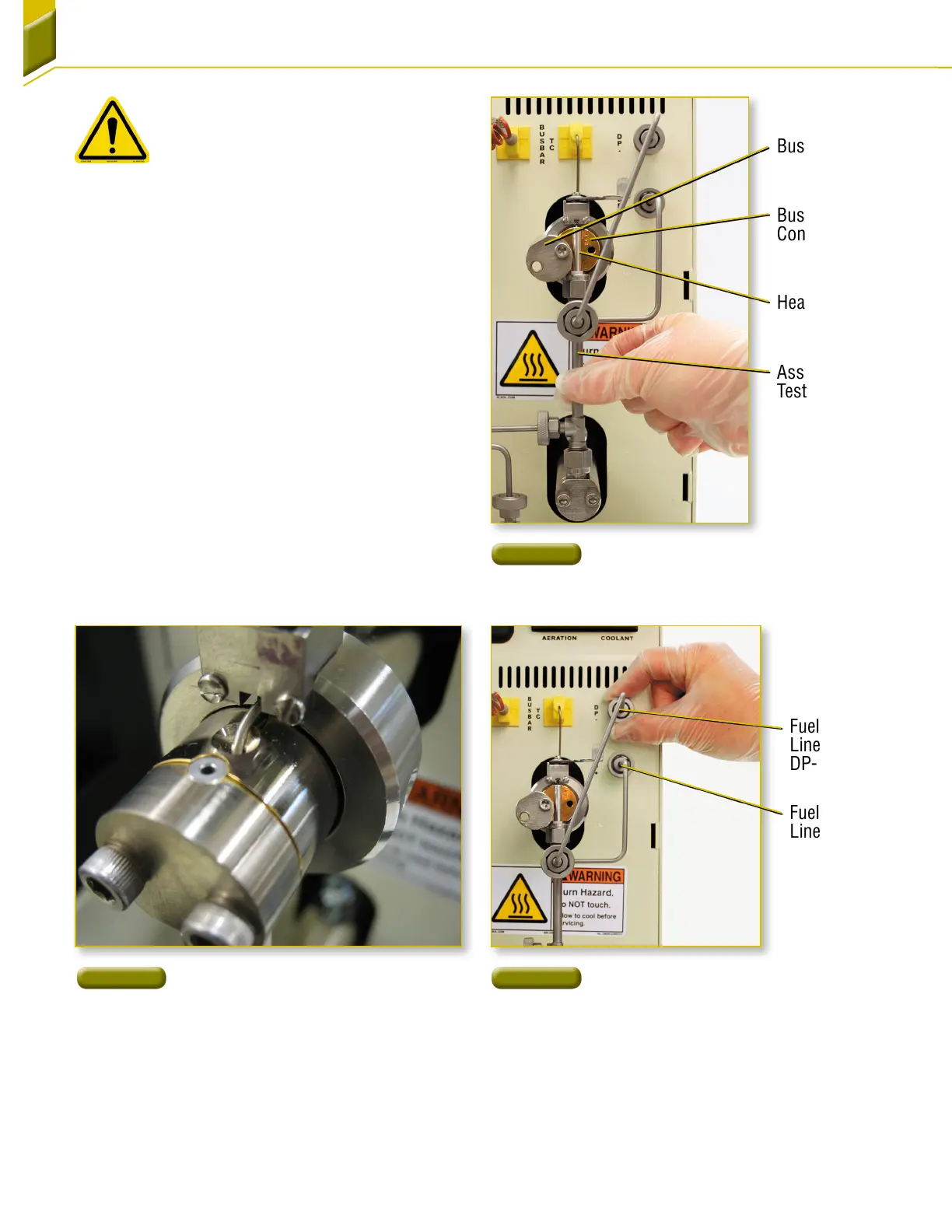
12. Install the assembled test section into the
sample test area [Figure20]. Place the assembled
test section in the groove between the bus bar
contacts and bus bar caps serial number side up.
Insert both right hand retaining screws and loosely
finger tighten.
13. Align the top of the heater tube so that it is flush
with the top of the bus bar contact [Figure21].
14. When the test section is properly aligned, tighten
the upper and lower bus bar screws with the
hexagon wrench provided.
15. Attach the fuel-out line to the DP- fitting and fuel
bypass line to the DP+ fittings [Figure22]. Finger
tighten the fittings.
Fuel-Out
Line To
DP- Fitting
Fuel Bypass
Line To DP+
Fitting
Figure 22
Fuel-Out and Fuel Bypass Lines
Figure 21
Tube Aligned With Top of
BusBar
Figure 20
Inserting Test Section Installation
Bus Bar
Contacts
Bus Bar Caps
Heater Tube
Assembled
Test Section