7
LW-401 Operation, Installation, and Maintenance ManualLW-401
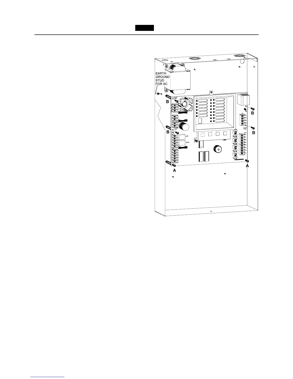
labeled A in Figure 6, leaving a
1
/4
inch gap between the standoff and
the head of the screw.
b. Place the slots on the bottom of the
LW41-MB on the two screws.
c. Secure the board in place by fasten-
ing the remaining four screws labeled
B to the metal hex standoffs.
d. Tighten the bottom two screws.
6. Optional modules. Refer to the specific
optional module Installation Instruction
sheet for the appropriate installation.
7. Before connecting any wire to its
screw terminal, refer to the Checkout
Procedure (page 27) and the LW-401
Connection Diagram, P/N 315-
096185FA. Prior to connecting wiring to
the Main board, ensure compliance to
maximum resistance in accordance with
the Field Wiring Checkout procedure,
page 27. Make sure that all power is off
before connecting leads.
8. Install power wiring. The LW-401 is
designed to operate from a 120 VAC, 60
Hz power source.
Use a dedicated circuitbreaker. Wire in
accordance with local codes and/or
Article 760 of the National Electrical
Code, NFPA 72, latest edition.
a. Run Earth Ground from a suitable
source to the Earth Ground stud on
the chassis (See Figure 6 for the
location of the stud). Secure in place
using the two #8 nuts provided.
Check local requirements. Conduit is
not an acceptable ground.
b. Connect the 120 VAC source and the
BLACK transformer wire leads
to TB1.
c. Connect the BROWN transformer
wire leads to TB6.
Figure 6
Mounting the LW41-MB