42
8 GbD-02
P3
P2
P1
7
5
6
3
2
1
P2
P3
P1
7
5
6
3
2
1
P1
P3
P2
7
5
6
3
2
1
P3
P2
P1
7
5
6
3
2
1
CT3
+SP
+RS
CT2
+SP
+RS
CT1
+SP
+RS
3
2
1
P2
P1
7
5
6
3
2
1
P2
P1
7
5
6
3
2
1
P1
P2
7
5
6
3
2
1
CT3
+SP
+RS
CT2
+SP
+RS
CT1
+SP
+RS
2
1
SR 40
SR 40
P1
7
5
6
3
2
1
P1
7
5
6
3
2
1
CT2
+RS
CT1
+RS
1
SR 40
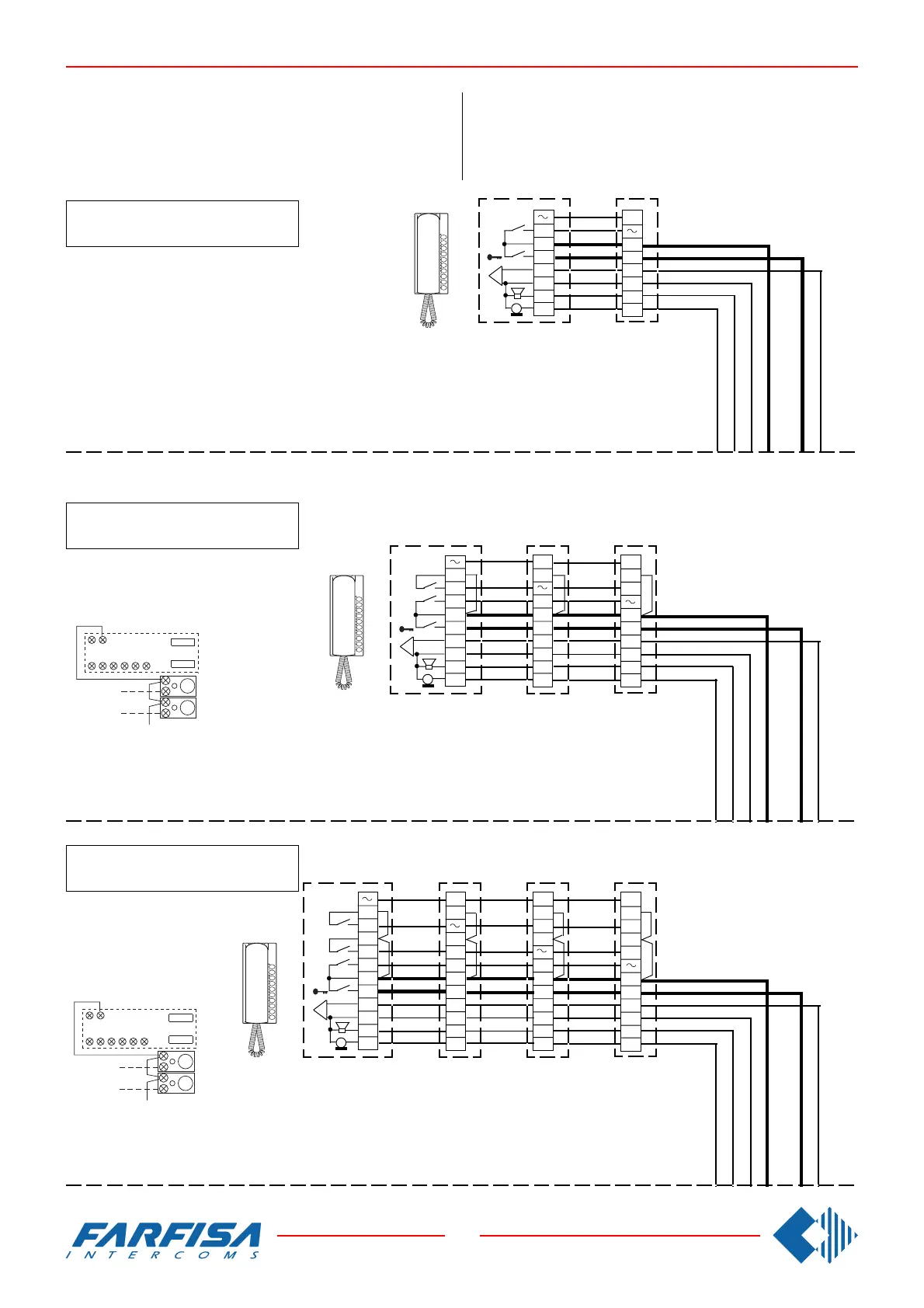
WORKING DIAGRAMS FOR INTERCOMMUNICATING SYS-
TEMS WITH A DOOR STATION AND COMMON CALL AND
ELECTRONIC BELL FOR INTERNAL CALLS.
Combine with the systems Si 230/5.
2 intercommunicating intercoms
2 Gegensprechhaustelefone
ANWENDUNGSSCHALTPLÄNE FÜR EINFAMlLIENHAUS
GEGENSPRECHANLAGEN MIT TÜRSTATION UND ELEK-
TRONISCHEM KLANGRUF FÜR INTERNRUFE.
Kombinierbar mit dem Schaltplan Si 230/5.
4 intercommunicating intercoms
4 Gegensprechhaustelefone
3 intercommunicating intercoms
3 Gegensprechhaustelefone
Connect one of the two terminals of the single button unit
to terminal 7.
Eine Anschlußklemme der Zusatztasten muß mit der
Klemme 7 verbunden werden.
CT4+SP+RS
Connect one of the two terminals of the single button unit
to terminal 7.
Eine Anschlußklemme der Zusatztasten muß mit der Klem-
me 7 verbunden werden.
9 7
2315P16
P2
P3
9 7
2315P16
P2
P3