3
8 GbD-'02
INTERCOMS /
HAUSTELEFONE
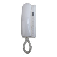
PT 510. Two-colour intercom for 4+1 systems
connected to one or more door stations. Com-
plete with push-button, spiral cord, buzzer,
electronic microphone. Wall-mounted with
screws or fixed to back box.
PT 510N. Colour: beige.
PT 510W. Colour: white.
Terminals
1 microphone
2 loudspeaker
3 ground
5 door release push-button (max 1A)
6 buzzer (absorption 0.2A)
9 electronic bell input
PT 510. Haustelefon Farbe schwarz/grau für
4+n Sprechanlagen mit eine oder mehreren
Türstationen. Mit einer Taste, Spiralschnur,
Summer und elektronischem Mikrofon. Aufputz
Wandmontage. Als Tischapparat verwendbar
mit Hilfe des Adapters Art.Nr.PT538.
PT 510N. Wie oben aber Farbe sandbeige.
PT 510W. Wie oben aber Farbe weiß.
Anschlußklemmen
1 Mikrofon
2 Lautsprecher
3 Masse
5 Taste Türöffner (max. 1A)
6 Summer (Stromverbrauch 0,2A)
9 Eingang elektronischer Rufton
Inside the intercom it can
be added both SM50
(privacy module) and
SR40 (electronic bell
module).
Im Haustelefon können
gleichzeitig beide Zu-
satzmodule SM50 und
SR40 eingebaut wer-
den.
921653
Project
Series
Serie
PT538. Table adaptor complete with ballast
base, connector, 13 wires cable. For Project
intercom series.
PT538. Tischadapter komplett mit beschwer-
ter Basis, Wandanschlussdose und Verbin-
dungskabel mit 13 Adern für max. 5 Funktions-
tasten. Für alle Haustelefone Serie Project.
PT502. Led module to indicate door-open.
PT502. Zusatzmodul LED für Türöffnungs-
anzeige oder andere Sonderfunktionen.
SR40
or /
oder
SM50
PT501
PT501
PT502
PT515
Note
We recommend to insert the LED module
PT502 and bell silencer module PT515 in the
bottom 2 seats marked by
and .
To insert them properly it's necessary to re-
move the guide of the button sliding from the
internal side of the base cover (see figure).
Bitte beachten
Wir empfehlen den Einbau des LED Moduls
PT502 und des Schalter Moduls PT515 in den
zwei letzteren mit
und gekennzeichneten
Einbaupositionen. Für den korrekten Einbau
müssen Sie die Tastenführungen auf dem
Gehäuseboden entfernen (siehe Bild).
83
182
60
 Loading...
