WITHOUT
COAX *
WITH COAX
46
(GB- '99)
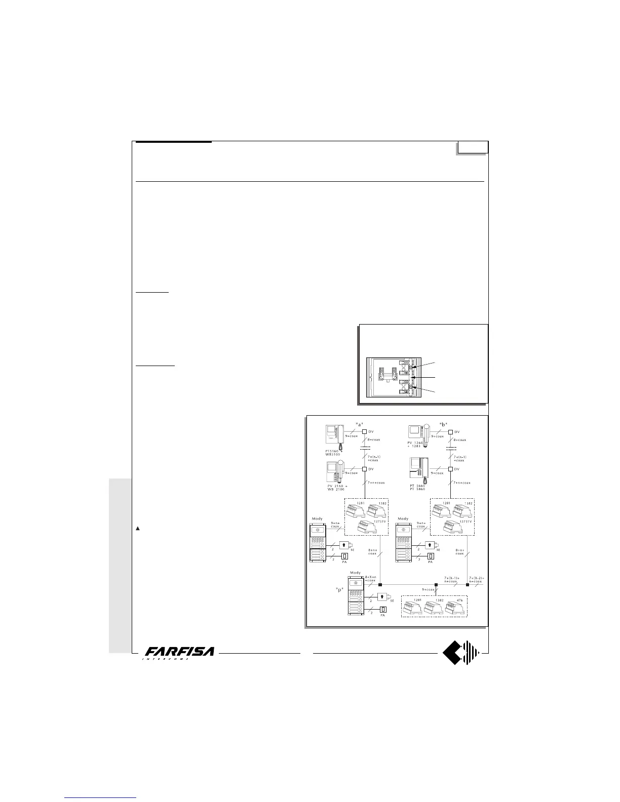
MULTI-WAY VIDEO-INTERCOM SYSTEM WITH AUXILIARY VIDEO ENTRANCES AND ONE MAIN VIDEO
ENTRANCE ACCORDING TO THE STAIRWAY
Diagram ref. Q.ty Article Description
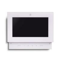
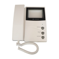
VC ... PT 5160 + WB 5100 Monitor FLAT + wall bracket
PT 5660 + WB 5600 + 1283 Monitor + wall bracket + back box
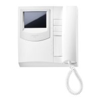
PT 5860 + WB 5600 Monitor reflex + wall bracket
PV 1260 + WB1200 + 1283 Monitor + wall bracket + back box
PV 2160 + WB 2100 Monitor FLAT + wall bracket
DV ... DV2-4 Video floor distributors
AV 1 476 Video distributor-amplifier
AL 1+X 1281 Stabilized power supply
TR 1+X 1382 Audio-Video Timer
DS X 1273TV Exchanger
PA 1+X ** Door release button
SE 1+X ** Electric door lock (12Vac-1A)
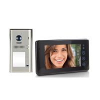
External door station
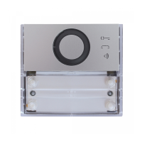
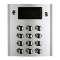
Mody series (see pages 16, 17, 18, 19 for the composition)
1 row 2 row
UR 1 +X MD40 MD40 Camera module
PB ... MD72-73-74 MD72-73-74 Module frames and with back box
1+X MD10-11-12 MD10-122-124 Modules for electric door speaker
... MD21 ÷ 24 MD222 ÷ 228 Button modules
... MD20 - 50 MD20 - 50 Blank and number modules
1+X MD82 ÷ 812 MD82 ÷ 812 Hood covers
1+X MD92 ÷ 912* MD92 ÷ 912* Rain shelters
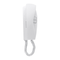
PE 1+X MD30 MD30 Electric door speaker
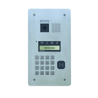
ErreP/R series (see pages 21, 22 for the composition)
UR 1+X 1385R Camera unit
PB 1+X RP... Push-button panel
... R... Push-button panel
1+X 290R/2 ÷ 290R/38 Rain shelters
PE 1+X 337C Electric door speaker
...According to the number of users.
X According to the number of auxiliary entrances.
* The protective shelters are to be used instead
of back boxes and decorative shields.
** Articles not provided by ACI Farfisa.
Si 5551
common buttons 1
and 2
to separate buttons
common cut here
common buttons 3
and 4
The push-button panel of the main video en-
trance must have separate commons. A com-
mon for every auxiliary entrance. The buttons of
Mody series can be divided in groups of 2.
* MODY *
ERREP/R
* PROJECT *
PUNTO
VIRGOLA *
SLIM
Multi-way systems
Working instructions
It is similar to the basic system described on page 28, but with the
following variations:
- The audio-video operations and the door lock release are
automatically switched at the time of the call or with the control
switch ON.
- The services towards the auxiliary video entrances are independ-
ent among themselves and therefore they can function at the same
time.
Note
The 75Ω resistance inserted between terminals 1 and 3 of
monitors is supplied with the product. It is not to be added.
- The A and F terminals of article 1382 can be connected to a
maximum of 6 lamps (24V-3W). If this number is exceeded, one or
more 12V transformers and an proper power will be required (type
PRS210).
- To have the control switch ON for the 3 video entrances it is
necessary to make the dashed line connections and use WB5160,
WB5660, WB2160, WB1260 wall brackets.
- The wall brackets are configurated to work without the audio
privacy, to restore it the jumper W1 must be moved (see pages 3,
5, 7, 9 and 10).
- In this system the control switch ON from the monitors can
interrupt a running communication, for this reason it is advisable to
interrupt it by means of a relay art.1471 (see page 25).
- For the cross section of the wires see the table on page 26.
- To connect the coaxial cable see pages 26 and 27.
 Loading...