WITHOUT C
OAX *
WITH
COAX
51
(GB- '99)
symbol for terminal
monitor PT5160,
PT5660, PT5860,
PV1260
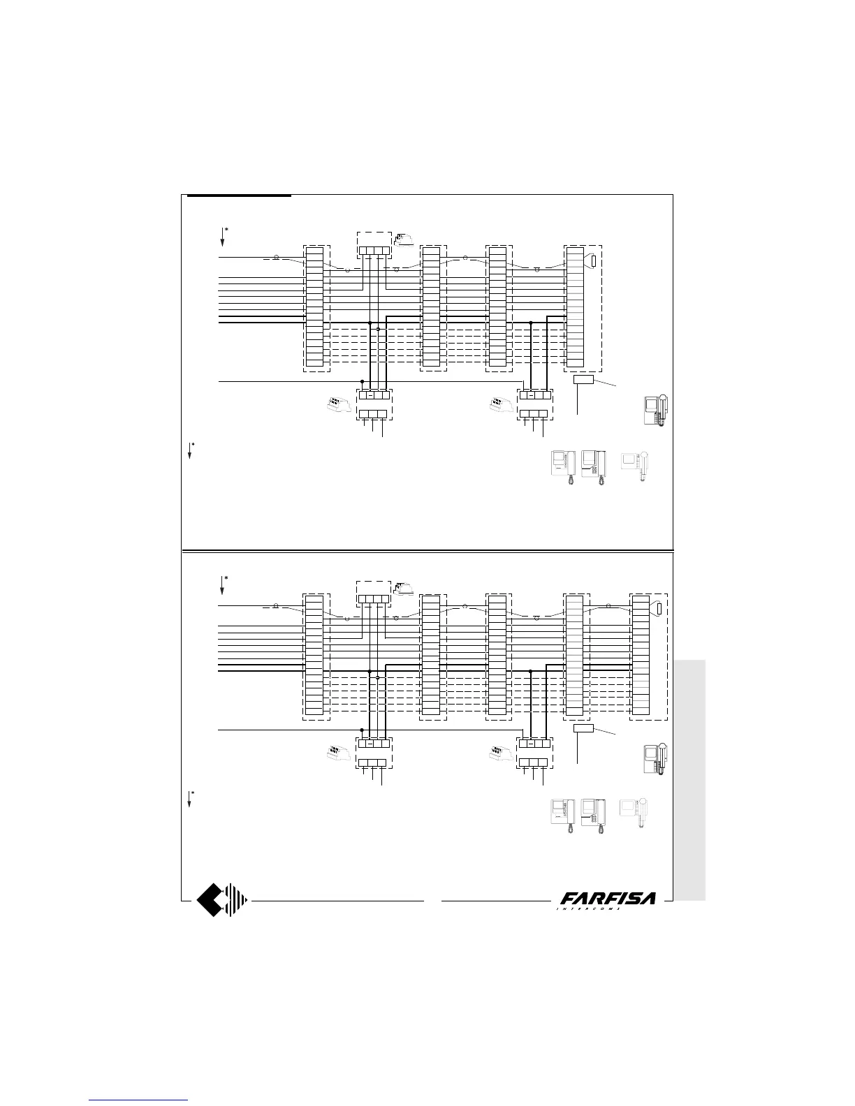
Working diagrams
* MODY * E
RREP/R *
PROJECT *
PUNTOVIRGOLA
* SLIM
1356
IN
IA+
AL
0
127V
230V
IA+
AL
0
127V
230V
VC4
8
1
3
1
4
9
10
11
12
13
14
2
X1
P1-T1
P2-T2
P3-T3
X2
P4-T4
8
1
3
1
4
9
10
11
12
13
14
2
X1
X2
P1-T1
P2-T2
P3-T3
P4-T4
VC1
Terminal I
(art.1382)
1471 VC2
8
1
3
1
4
9
10
11
12
13
14
2
X1
P1-T1
X2
P2-T2
P3-T3
P4-T4
8
1
3
1
4
9
10
11
12
13
14
2
X1
P1-T1
P2-T2
X2
P3-T3
P4-T4
VC3
VC =
PT5160 + WB5100
PT5660 + WB5600 + 1283
PT5860 + WB5600
PV2160 + WB2100
PV1260 + WB1200 + 1283
or, if intercommunicating
PT5160 + WB5160
PT5660 + WB5660 + 1283
PT5860 + WB5660
PV2160 + WB2160
PV1260 + WB1260 + 1283
1281
1281
75Ω
P1-T1
To have the intercommunicating service, make the con-
nections which have been drawn with a dashed line, then
insert in the timer, art.1382, the module for intercommuni-
cating, art.1443, which is included in the video kit (see
page 23).
ADDITIONAL DIAGRAM FOR 4 PARALLEL MONITORS
Graphic overlap point for
extension of diagram (see
page 48).
symbol for terminal
monitor PV2160
symbol for terminal
monitor PT5160,
PT5660, PT5860,
PV1260
1356
IN
IA+
AL
0
127V
230V
IA+
AL
0
127V
230V
VC4
8
1
3
1
4
9
10
11
12
13
14
2
X1
P1-T1
P2-T2
P3-T3
X2
P4-T4
8
1
3
1
4
9
10
11
12
13
14
2
X1
X2
P1-T1
P2-T2
P3-T3
P4-T4
VC1
Terminal I
(art.1382)
1471 VC2
8
1
3
1
4
9
10
11
12
13
14
2
X1
P1-T1
X2
P2-T2
P3-T3
P4-T4
8
1
3
1
4
9
10
11
12
13
14
2
X1
P1-T1
P2-T2
X2
P3-T3
P4-T4
VC3
VC =
PT5160 + WB5100
PT5660 + WB5600 + 1283
PT5860 + WB5600
PV2160 + WB2100
PV1260 + WB1200 + 1283
or, if intercommunicating
PT5160 + WB5160
PT5660 + WB5660 + 1283
PT5860 + WB5660
PV2160 + WB2160
PV1260 + WB1260 + 1283
1281
1281
8
1
3
1
4
9
10
11
12
13
14
2
X1
P1-T1
P2-T2
P3-T3
P4-T4
X2
VC5
75Ω
P1-T1
To have the intercommunicating service, make the con-
nections which have been drawn with a dashed line, then
insert in the timer, art.1382, the module for intercommuni-
cating, art.1443, which is included in the video kit (see
page 23).
ADDITIONAL DIAGRAM FOR 5 PARALLEL MONITORS
Graphic overlap point for
extension of diagram (see
page 48).
symbol for terminal
monitor PV2160




 To Next Page