WITHOUT
COAX *
WITH COAX
54
(GB- '99)
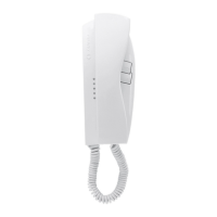
symbol for terminal
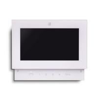
monitor PV2160
* MODY *
ERREP/R
* PROJECT *
PUNTO
VIRGOLA * S
LIM
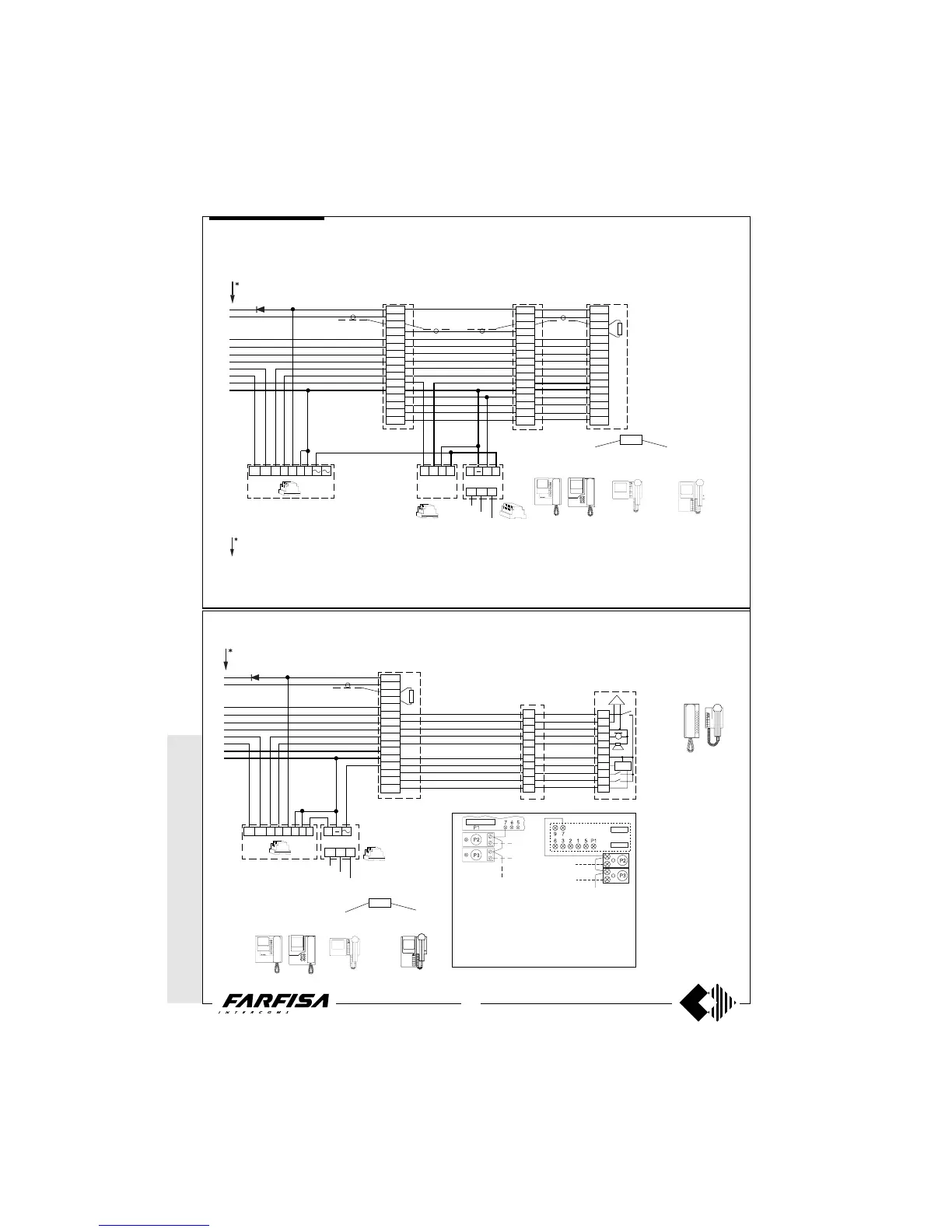
Working diagrams
ADDITIONAL DIAGRAM FOR MULTI-WAY SYSTEMS WITH 3 INTERCOMMUNICATING PARALLEL MONITORS
ADDITIONAL DIAGRAM FOR MULTI-WAY SYSTEMS WITH 1 MONITOR AND 2 PARALLEL INTERCOMS
P1-T1
VC =
PT5160 + WB5100
PT5660 + WB5600 + 1283
PT5860 + WB5600
PV2160 + WB2100
PV1260 + WB1200 + 1283
or, if intercommunicating
PT5160 + WB5160
PT5660 + WB5660 + 1283
PT5860 + WB5660
PV2160 + WB2160
PV1260 + WB1260 + 1283
Graphic overlap point for
extension of diagram (see
page 48).
Note
In all the intercommunicating intercoms, con-
nect one of the two terminals of the single
button group to terminal 7.
In all intercoms take out the mobile jumper
which links the terminals 3 and 7 (or cut the W1
jumper in the Project models). Then apply the
electronic bell SR40, and the button groups.
PT520PV260
symbol for terminal
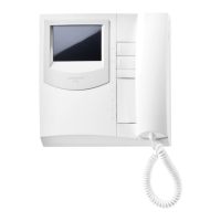
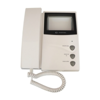
monitor PT5160,
PT5660, PT5860,
PV1260
5
6
3
1
2
7
X1
P1
X2
P2
75Ω CT2
CT1
5
6
3
1
2
7
X1
P1
P2
X2
SR40
8
1
3
1
4
9
10
11
12
13
14
2
X1
X2
P1-T1
P2-T2
VC
(Diode 100V-1A / type 1N4002)
230V
AL
0
127V
+
13a 12a 12 13 14 O F B
2443
SA
PRS220
CT =
PT510
PV100
924
or, if intercommunicating
PT520 + SR40 + PT501
PV260 + SR40 + SP10
VC2
8
1
3
1
4
9
10
11
12
13
14
2
X1
P1-T1
X2
P2-T2
8
1
3
1
4
9
10
11
12
13
14
2
X1
P1-T1
P2-T2
X2
VC3
8
1
3
1
4
9
10
11
12
13
14
2
X1
X2
P1-T1
P2-T2
VC1
P1-T1
VC =PT5160 + WB5100
PT5660 + WB5600 + 1283
PT5860 + WB5600
PV2160 + WB2100
PV1260 + WB1200 + 1283
or, if intercommunicating
VC =PT5160 + WB5160
PT5660 + WB5660 + 1283
PT5860 + WB5660
PV2160 + WB2160
PV1260 + WB1260 + 1283
75Ω
13a 12a 1 2 1 3 14 O F
2443
SA
IA+
AL
0
127V
230V
2536
IN
1471
(Diode 100V-1A / type 1N4002)
1281
symbol for terminal monitor PT5160,
PT5660, PT5860, PV1260
symbol for terminal monitor
PV2160
 Loading...