(!) The controls to stabilize the vehicle are in conformity with the safety
directives and enable the operator to activate the lateral extension of the
outriggers (outrigger supports and rams) only from the side where he can
visually check the operation.
The special construction concept of the outrigger control group
which combines the functions of an 8 positions deviator with
those of a distributor segment, allows to use the control lever for
selecting and operating the supports and the outrigger rams.
- The selection (support or ram) is effected, like on a devia-
tor, by positioning the lever on the corresponding position
indicated by the function schematic (plates DE2298 and
DE2297) placed on the controls.
- The control is effected by operating the lever like on a distri-
butor; the stability of the selected position is guaranteed by
an internal device.
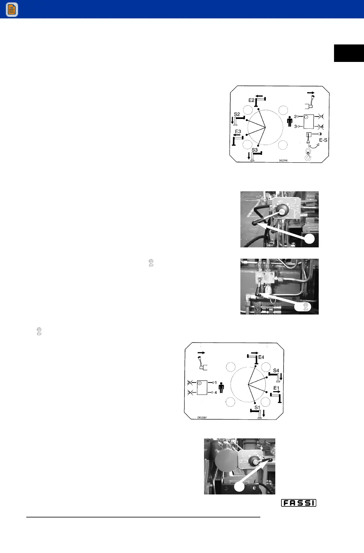
The extension and re-entering of the support and outrigger rams
indicated on the fig. 13-14 coincide with what indicated on the plates
DE2298 and DE2297 placed in dual side position on the base.
The symbols reported at side of each lever indicate the operating
levers in relation to their movement.
Lever function D - C
- Lever D Deviator crane - outriggers ( - E/S). Fig. 15a - 15b
- Lever C Multifunction deviator for selecting and operating the
supports and the outrigger rams of the crane as well as the
supplementary outriggers. Fig. 15-16
Control for outrigger support extension for the crane and the sup-
plementary outriggers.
- Position lever D of oil diverter crane-outriggers
( - E/S) on E/S. Fig. 15b
- Open all the taps of the valves placed on the
outrigger rams fig. 17.
- Disengage the locking devices of the outrigger
supports by putting the levers A from the
position of the fig. 18 to the one of the fig. 18a.
Crane distributor side DE2298 fig. 15.
- Select the outrigger support E2 positioning the
lever C of the multifunction deviator on E2.
- Operate the lever to extend the support E2.
- Select the outrigger ram S2 positioning the
lever C on S2.
- Operate the lever to control the ram descent
S2.
- Select the support E3 positioning the lever C
on E3.
- Operate the lever to extend the support E3.
- Select the ram S3 positioning the lever C on
S3.
- Operate the lever to control the ram descent
S3.
c IX
17
CONTROLS
TO STABILIZE
THE VEHICLE
F 240
Distributor side
fig. 13
C
fig. 15
fig. 15a
D
Double control side
fig. 14
C
fig. 16