N.B. The lever, if in other positions, does not allow any operations as a
security device keeps it in free position.
Crane double control side DE2297 fig.14-16
- Select the support E1 positioning the lever C on E1.
- Operate the lever to extend the support E1.
- Select the ram S1 positioning the lever C on S1.
- Operate the lever to control the ram descent S1.
- Select the support E4 positioning the lever C on E4.
- Operate the lever to extend the support E4.
- Select the ram S4 positioning the lever C on S4.
- Operate the lever to control the ram descent S4.
N.B. The lever, if in other positions, does not allow any operations
as a security device keeps it in free position.
(!) ATTENTION (!)
During the stabilisation operations, for each outrigger ram, it is
recommended to DESCENT the outrigger as last manoeuvre.
(!) ATTENTION (!)
The complete extension of the outrigger supports is visually indicated by
the yellow triangle which is found at the end of the beam. (Fig. 18b)
The stabilization has to be carried out with care and gradually keeping
the vehicle in horizontal levelled condition to prevent springs overloads
and chassis torsions.
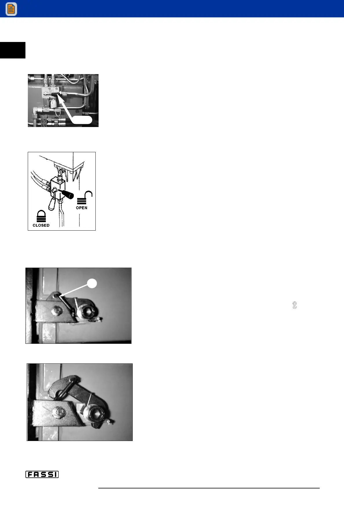
After having completed the descent and stabilisation manoeuvres, close
the taps of the valves placed on the outrigger rams.
Manoeuvres for re-entry of the crane outriggers and
supplementary outriggers within the overall vehicle
width after crane use.
- Position lever D of oil diverter crane-outriggers ( - E/S)
on E/S. Fig. 15b
- Open all the taps of the valves placed on the outrigger rams
(fig. 17).
(!) WARNING (!)
Under no circumstances put the hands on the locking devi-
ces of the outrigger supports; the device re-hook (lever A
from position of fig. 18b to fig. 18) is automatic.
Crane distributor side
- Select the outrigger ram S2 positioning the lever C on S2.
- Operate the lever to control the re-entry of the ram S2.
- Select the outrigger support E2 positioning the lever C on
E2.
- Operate the lever to control the re-entry of the support E2.
- Select the ram S3 positioning the lever C on S3.
- Operate the lever to control the re-entry of the ram S3.
- Select the support E3 positioning the lever C on E3.
- Operate the lever to control the re-entry of the support E3.
NB The lever, if in other positions, cannot be operated as a
safety device keeps it in neutral position.
c IX
CONTROLS
TO STABILIZE
THE VEHICLE
F 240
18
A
fig. 18
fig. 18a
fig. 17
fig. 15b
D:E-S