c X
CONTROLS TO OPERATE
THE CRANE
F 240
25
Manoeuvres to unfold the crane into a working condition (fig. 30)
— Engage the power take off.
— Stabilize the vehicle as described on page 00.
(!) Operate from ground control distributor side (!)
— Operate the lever I (re-entry) to ensure that the
extension booms are re-entered.
— Before lifting the inner boom, be sure that the outer ram is closed (operate
the lever H re-entry function).
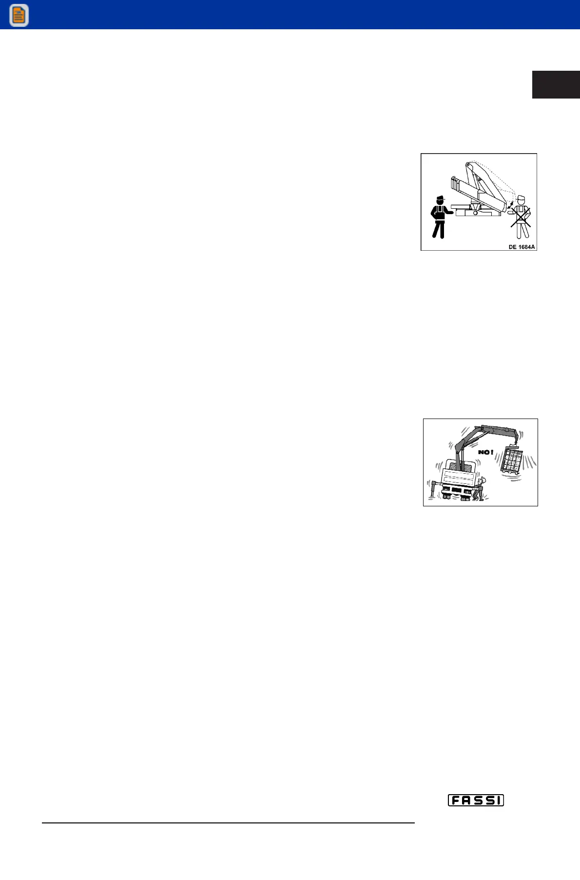
— Lift the inner boom over the horizontal line, by operating lever G whilst paying
attention to the position of the booms (fig. 30a) (in case of operation from the
double control side).
— Open the outer boom to the “horizontal” position by operating lever H.
— (Eventually) extend the booms of the crane by operating lever I.
— Position the hook on the vertical line above the load, operating lever F (rotation).
Manoeuvres to fold the crane into the rest condition
(!) Operate from ground control distributor side (!)
— Fold the extension booms to their stroke end.
— Lift the inner boom to its stroke end.
— Fold the outer boom to its stroke end.
— Operate the rotation control until the arrows placed on the base and on the
column (dust cover) coincide.
— Fold the inner boom to its stroke end, paying attention that the rest locating pin
lines up with its seat and to the boom movements (fig. 30a) (in case of operation
from the double control side) .
— Lift and re-enter the outriggers to within the overall vehicle width as described
at page 20.
Load manoeuvres
(!) Before manoeuvering the load, verify that the working area is suitable for your crane.
The lifting curves of the capacity plate indicate the maximum load that the crane
can lift at a certain radius and at a certain height.
To utilize the maximum capacity of the crane, it is necessary to position the
inner boom as indicated on the capacity plate; the coloured symbols on the
inner boom and column must coincide.
During load handling, do not exceed the reach limits given, or the load indicated on
the above mentioned charts.
If the limits are exceeded, the load limiting device, permitting the slow descent
of one of the two, or both, lifting rams (or if the jib is fitted: the jib outer ram) will
be immediately activated.
To stop the load descent, it is compulsory to raduce the load radius towards the column,
operating the control lever to re-enter the boom extension rams of the crane (or jib exten-
sion rams) or with an alternative manoeuvre which reduce the moment on the column axis.
(!) This operation must be carried out within and not over 5 seconds from the
beginning of the load descent.
(!) The presence of the load limiting device does not release the user from the
obligation to respect what is indicated on capacity plates and lifting curves.
(!) ATTENTION (!)
Carefully check the stability of the vehicle within all the working area paying particular
attention to the area immediately in front of the driver’s cabin which is usually less stable.
Crane version with lifting moment limiting device (optional)
During load handling, do not exceed the reach limits given, or the load indicated on
the capacity plates and lifting curves. If the limits are exceeded, the lifting moment
limiting device, allowing all manoeuvres, which reduce the lifted load within the per-
mitted reach limits and forbid all other manoeuvres, will be immediately activated.
(!) The presence of the lifting moment limiting device does not release the
user from the obligation to respect what is indicated on capacity plates
and lifting curves.
fig. 30a