Advanced Function Instruction
7-26
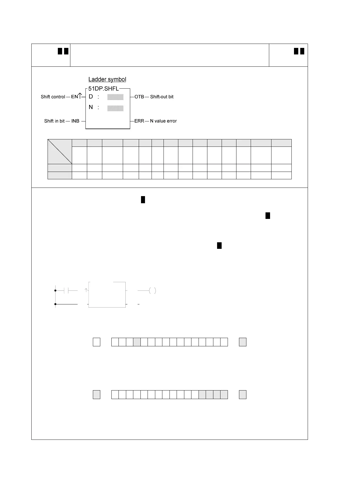
FUN 51 D P
SHFL
SHIFT LEFT
FUN 51 D P
SHFL
D : Register to be shifted
N : Number of bits to be shifted
N, D may combine with V, Z, P0~P9 to serve
indirect address application
WX WY WM WS TMR CTR HR IR OR SR ROR DR K XR
Range
Ope-
rand
WX0
∣
WX240
WY0
∣
WY240
WM0
∣
WM1896
WS0
∣
WS984
T0
∣
T255
C0
∣
C255
R0
∣
R3839
R3840
∣
R3903
R3904
∣
R3967
R3968
∣
R4167
R5000
∣
R8071
D0
∣
D4095
1 1
∣ or ∣
16 32
V、Z
P0~P9
D ○ ○ ○ ○ ○ ○ ○ ○* ○* ○ ○
N ○ ○ ○ ○ ○ ○ ○ ○ ○ ○ ○ ○ ○ ○
z When shift control "EN" = 1 or "EN↑" ( P instruction) has a transition from 0 to 1, will shift the data of the D
register towards the left by N successive bits (in ascending order). After the lowest bit B0 has been shifted
left, its position will be replaced by shift-in bit INB, while the status of shift-out bits B15 or B31 ( D instruction)
will appear at shift-out bit "OTB".
z If the operand is 16 bit, the effective range of N is 1~16. For 32 bits ( D instruction) operand, it is 1~32.
Beyond this range, will set the N value error flag "ERR" to 1, and do not carry out this instruction.
EN
N :
OTB
Y0
51P.SHFL
X0
INB
D :
4
R 0
ERR
z The instruction at left shifts the data in register R0
towards the left by 4 successive bits. The results are
shown below.
Y0
B15
R0 B0
INB
← 0 0 1 1 001011110000 ← 1
* △
Ø
X0=
Y0
B15
R0 B0
INB
1 0 0 1 0 111100001 1 1 1 1
* △ △ △ △ △