FLT
®
Series FlexSwitch
TM
OPERATION
Fluid Components International LLC 17
3 OPERATION
Caution:
The control circuit contains electrostatic discharge (ESD) sensitive devices. Use standard ESD precautions when handling the
control circuit. See Section 2, Operation, for ESD details.
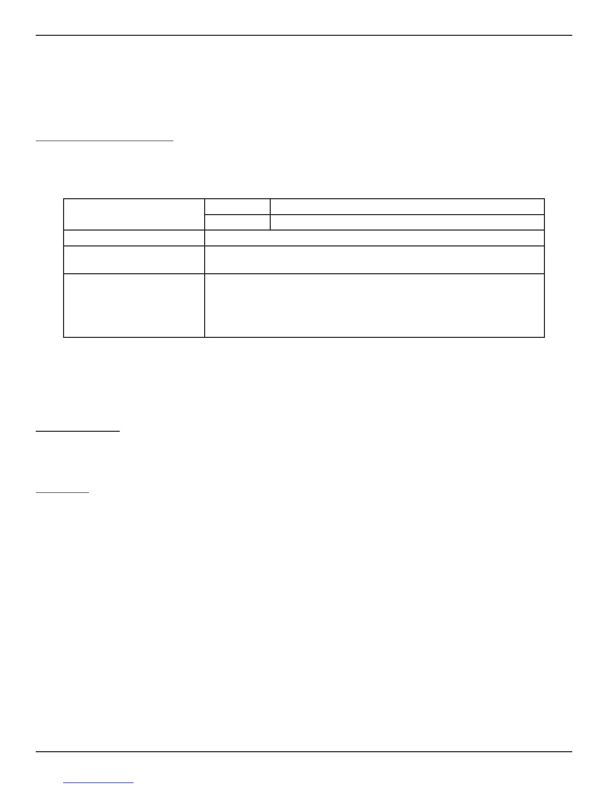
Factory Default Jumper Conguration
Unless a custom factory setup or calibration is specified, the instrument is delivered in a standard factory configuration. The standard default
jumper configuration is shown in Table 3-1.
Heater Power
FLT93S/FLT93B 0.75 watts for air or liquid level applications. (J13)
FLT93F 0.25 watts for air or liquid level applications. (J14)
Number of Alarms Two (J23). Each alarm has one set of SPDT contacts
Alarm No. 1 Red LED
Setpoint Pot, R26
Set to monitor flow or level signals (J20). Relay energized at flow or wet (J27)
Alarm No. 2 Green LED
Setpoint Pot, R25
Set to monitor temperature signals (J19). Relay energized below temperature (J25).
Setpoint at approximately:
350 °F (121 °C) for standard temperature,
500 °F (260 °C) for medium temperature,
850 °F (454 °C) for high temperature (FLT93S Only)
Table 3-1 Standard Jumper Default Configuration
If the order includes custom factory setup and calibration, leave all settings alone. The instrument is ready for service without changes.
If custom factory setup or calibration was not ordered, configure the control circuit using the jumper tables (Tables 3-2 to 3-6) and then follow
the setpoint adjustment section that is appropriate for the application.
Conguration Jumpers
If the order did not specify for the control circuit to be factory configured, the standard configuration can be changed using Figure 3-1 and
Table 3-1 through Table 3-6. The factory default configuration is shown underlined.
Heater Cut-Off
The 5208 control circuit has a heater cutoff switch that limits the skin temperature of the sensing element to a temperature differential of
approximately 150 °F (66 °C) above the process temperature. In the case where the instrument is used as a gas flow switch, and the heater
wattage is set too high, the temperature differential between the RTDs may exceed the usable input range of the control circuit. The usable
input range can also be exceeded in the case where the instrument is used in liquid flow applications where the heater wattage is set at
the highest value, and the sensing elements go dry. When the temperature differential is less than 150 °F (66 °C) the heater automatically
turns back on. The yellow power indicator LED (DS3) turns on and off with the heater for a visual indication of the heater state. The LED will
alternate between on and off (i.e., flashing) until the condition is corrected.
The reason for operating in the above extreme conditions is to insure that the input signal range is at the widest point making the alarm
setpoint adjustment easier to perform. If the heater does cycle the operator may need to use the next lower wattage setting.
In some applications it is desirable to set the heater wattage high, even though the sensing element goes into the heater cutoff mode. An
example is when the instrument is used to detect the interface of two liquids. These liquids may have viscosities that will have signals very
close to each other. In order to have the maximum signal difference between the signals the heater wattage is set to its maximum. If the
sensing element detects a dry condition the control circuit will indicate a heater cutoff condition. The sensing element will not be damaged
if it is left dry with the maximum heater wattage. The alarms can be set so one alarm will switch at the interface and one alarm can detect
when the element goes dry.