OPERATION FLT
®
Series FlexSwitch
TM
22 Fluid Components International LLC
6. Disconnect the voltmeter from P1.
7. Replace the enclosure cover.
Note:
The alarm can be set for a specific flow rate. Follow the Air/Gas Flow Applications procedure up to step 7 except establish
the specific flow rate rather than the normal flow. The output signal will be the setpoint value. Determine whether the alarm
should actuate with decreasing or increasing flow and skip to the appropriate step 4 in Detecting Decreasing Flow or Detect-
ing Increasing Flow, respectively. Enter the specific flow rate value as the setpoint. Then follow the Continue With the Air/
Gas Flow Procedure steps.
The default relay logic configuration is for the relay coil to be de-energized when the flow signal voltage is greater than the
setpoint value; i.e., in a normal process flow condition the relay coil is energized if the alarm has been set for low-flow detec-
tion and de-energized if the alarm has been set for high flow detection. It is recommended to have the relay coils energized
when the process condition is normal. This lets the relay go into a fail-safe alarm state in case of a power failure.
Wet/Dry Liquid Level Applications
1. Remove the instrument’s enclosure cover.
2. Ensure the configuration jumpers on the control circuit are correct for this application. See Tables 3-2 through 3-6.
3. Make sure the input power is wired correctly (see Section 2).
4. Apply power to the instrument. Verify the yellow LED is on. Allow fifteen minutes for the instrument to warm-up.
5. Verify the Mode switch is in the RUN position.
6. Attach a DC voltmeter to P1 with the positive (+) lead to position one (red) and the negative (-) lead to position two (blue).
7. Raise the process fluid level so the sensing element is wet.
8. Allow the output signal to stabilize and record the wet condition value.
Wet Condition Signal = ________ volts DC
Note:
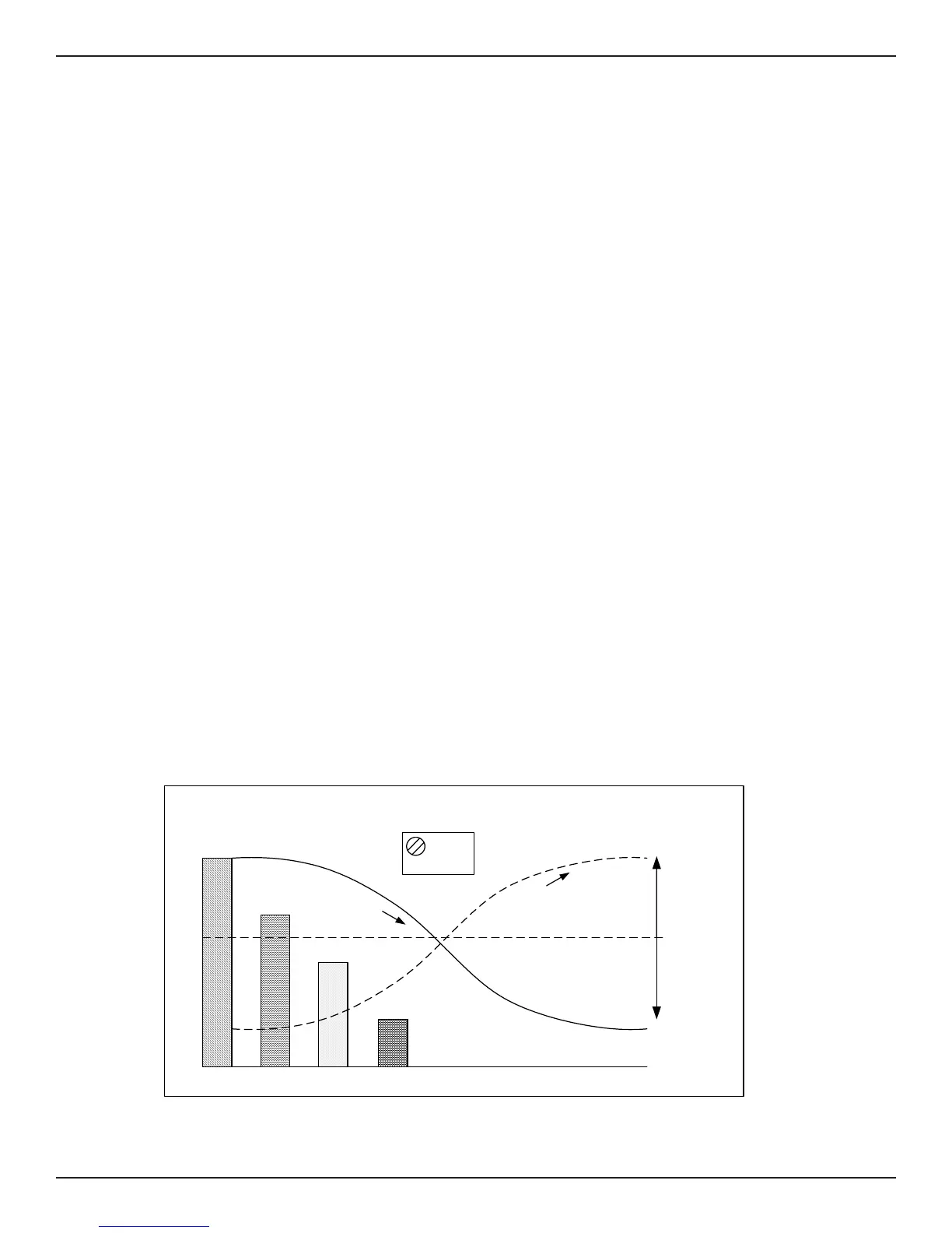
The output signal at P1 is relative to the type of process media detected. See Figure 3-4.
9. Lower the process fluid level so the sensing element is dry.
10. Allow the output signal to stabilize and record the dry condition value. Observe that the dry signal is greater than the wet signal.
Dry Condition Signal = ________ volts DC
Figure 3-4. Level Application Signal Output
SET POINT
TIME
OUTPUT VOLTAGE
AIR OR GAS
OIL
WATER
LED ON
ABOVE SETPOINT
LED OFF
BELOW SETPOINT
R25 AND R26
Adjust
Clockwise,
Turns
LED ON
Adjust
Counter-
clockwise,
Turns
LED OFF
FIELD ADJUSTABLE
SET POINT
0
Potentiometer
(POT)
DIESEL
A
I
R
T
O
W
A
T
E
R
WA
T
E
R
T
O
AI
R
C00070-1-2