FLT
®
Series FlexSwitch
TM
OPERATION
Fluid Components International LLC 21
Detecting Increasing Flow (High Flow Alarm)
1. Establish the excessive process flow condition and allow the signal to stabilize.
2. Record the high flow signal. Observe that the high flow signal is less than the normal flow signal.
High Flow Signal = ________ volts DC
3. Determine the setpoint by calculating the average of the normal (step 8, page 17 - Air/Gas Flow Applications) and high flow output
signals; e.g., if the normal signal is 2.000 volts and the high flow signal is 1.000 volts, then the calculated setpoint would be 1.500 volts.
Record this value.
Calculated Setpoint = ________ volts DC
Note:
The calculated setpoint must be at least 0.50 volts less than the normal signal to ensure that the alarm will reset.
4. Move the Mode switch to the CAL position.
5. Adjust the calibration potentiometer (R24) until the voltmeter equals the calculated setpoint.
6. For the appropriate alarm, determine whether the status LED is on or off (red for Alarm No. 1 or green for Alarm No. 2). If the LED is on, turn
the setpoint adjustment potentiometer (R26 for Alarm No. 1 or R25 for Alarm No. 2) slowly counterclockwise just until the LED turns off.
OR
If the LED is off, turn the setpoint adjustment potentiometer (R26 for Alarm No. 1 or R25 for Alarm No. 2) clockwise until the LED turns on
and then turn pot slowly counterclockwise just until the LED turns off.
Continue With The Air/Gas Flow Applications Procedure
1. Move the Mode switch to the RUN position.
2. Establish the normal process flow condition. For low-flow alarm setups, verify that the status LED is off. For high flow alarm setups, verify
that the status LED is on.
3. Establish the process alarm condition and monitor the voltmeter display.
4. When the output signal passes through the calculated setpoint value, verify that the status LED turns on for low-flow alarms, or turns off
for high flow alarms, and that the relay contacts change state.
5. Reestablish the normal process flow condition. Verify that the LED and the relay contacts reset.
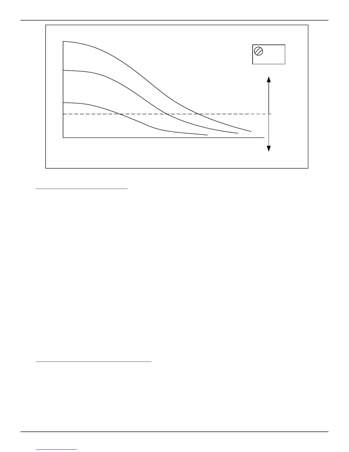
Figure 3-3 Flow Application Signal Output
SET POINT
FLOW
OUTPUT VOLTAGE
AIR OR GAS
OIL
WATER
LED ON
ABOVE SETPOINT
LED OFF
BELOW SETPOINT
R25 AND R26
Adjust
Clockwise,
Turns
LED ON
Adjust
Counter-
clockwise,
Turns
LED OFF
FIELD ADJUSTABLE
SET POINT
0
Potentiometer
(POT)
C00204-1-2