OPERATION FLT
®
Series FlexSwitch
TM
34 Fluid Components International LLC
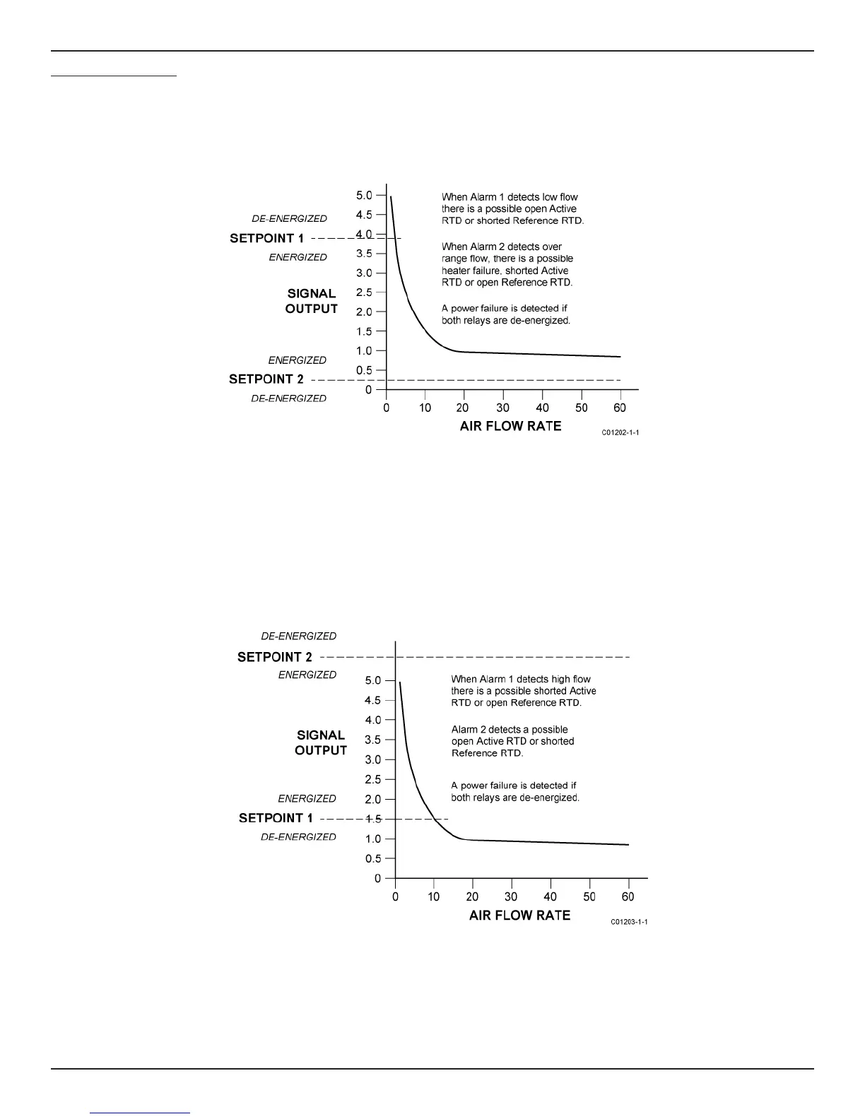
Fail-Safe Alarm Setting
These procedures set the second relay to detect component failure (fail-safe).
Low Flow Alarm Settings
Install the following jumpers for the low flow fail-safe setup: J18, J20, J23, J24, J27.
The following information is assumed:
Relay is de-energized in the ALARM condition.
Alarm 1 setpoint is adjusted for desired low flow alarm velocity or signal.
Alarm 2 setpoint is adjusted slightly below minimum signal output (over range flow).
High Flow Alarm Settings
Install the following jumpers for the high flow fail-safe setup: J18, J20, J23, J25, J26.
The following information is assumed:
Relay is de-energized in the ALARM condition.
Alarm 1 setpoint is adjusted for desired high flow alarm velocity or signal.
Alarm 2 setpoint is adjusted above maximum signal output (under range flow not to exceed 7.0 volts).
Figure 3-5. Low Flow Fail-Safe Alarm
Figure 3-6. High Flow Fail-Safe Alarm