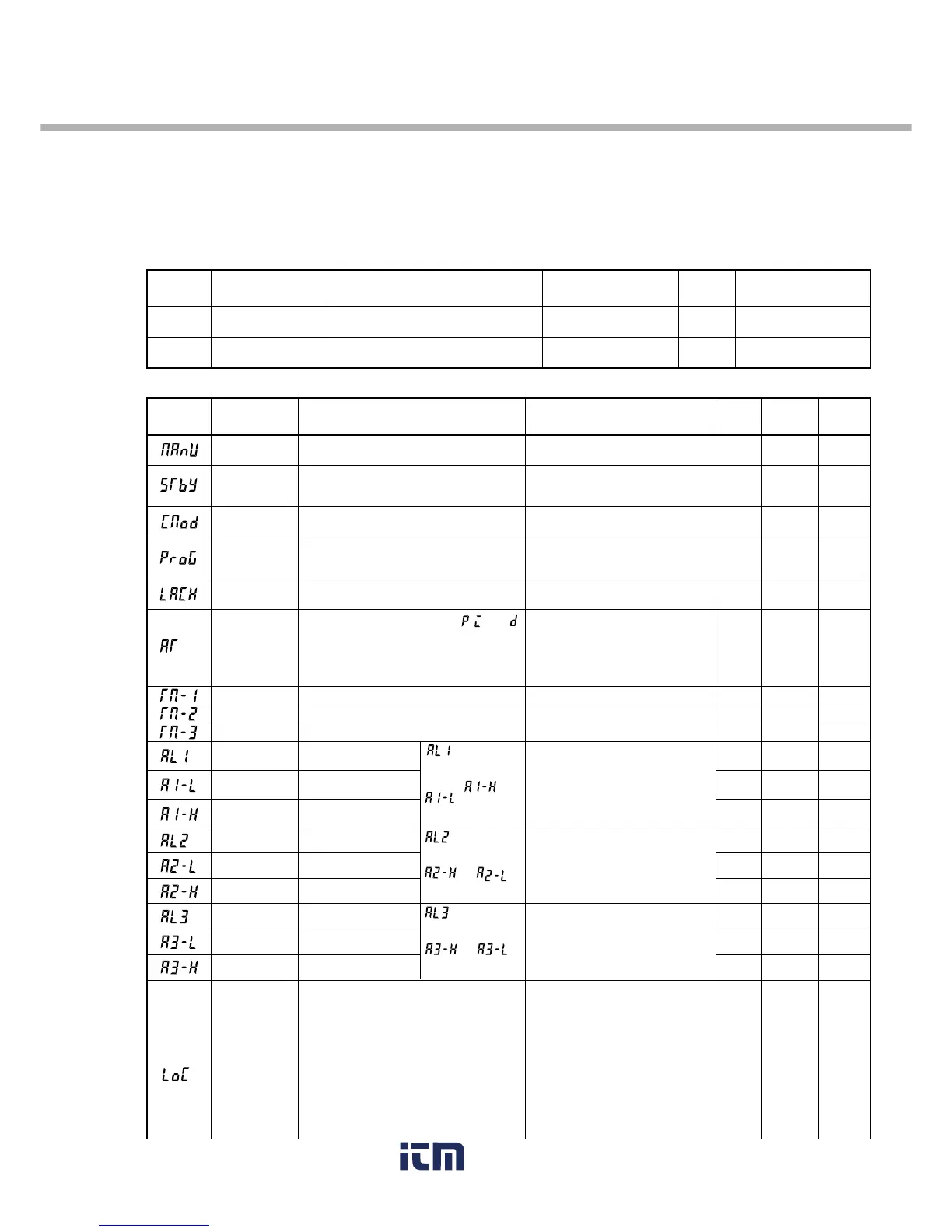
Parameter
display symbol
User’s
set value
Reference
page
Parameter name
Description
Setting range and
factory default setting (*)
Parameter
mask DSP
Manual mode
selection
Switches between Auto and Manual operation
modes.
oN: Manual mode
oFF: Auto mode*
0: All settings are changeable both from
the face panel and via communication.*
1: All settings are unchangeable from the
face panel, but changeable via
communication.
2: Only the SV is changeable from the
face panel, and all settings are
changeable via communication.
3: All settings are changeable from the
face panel, but unchangeable via
communication.
4:
All settings are unchangeable from the
face
panel or
via
communication.
5:
Only the SV is changeable from the
face
panel, but all settings are unchangeable
via
communication.
When the alarm type is absolute value:
0 to 100%FS (*:10)
When the alarm type is deviation:
-100 to 100%FS (*:10)
When the alarm type is absolute value:
0 to 100%FS (*:10)
When the alarm type is deviation:
-100 to 100%FS (*:10)
When the alarm type is absolute value:
0 to 100%FS (*:10)
When the alarm type is deviation:
-100 to 100%FS (*:10)
- (Unit: seconds)
- (Unit: seconds)
- (Unit: seconds)
0: OFF (Resets the auto-tuning or does
not use it.)*
1: ON (Performs the auto-tuning in the
SV standard type.)
2: ON (Performs the auto-tuning in
low PV type (SV value-10%FS).)
0: Keeps the alarm latch.*
1: Opens up the alarm latch.
oFF: Stop*
rUn: Start
HLd: Hold
rEM: Remote
LoCL: Local
oN: Control standby
(Output: OFF, Alarm: OFF)
oFF: Control RUN*
Upper limit value
of alarm 3
Ramp-soak
control
Sets the upper limit value at
which alarm 3 is detected.
Specifies whether or not to allow the change of
parameters.
Lower limit value
of alarm 3
Sets the lower limit value at
which alarm 3 is detected.
Set value of
alarm 3
Sets the value at which
alarm 3 is detected.
Upper limit value
of alarm 2
Sets the upper limit value at
which alarm 2 is detected.
Lower limit value
of alarm 2
Sets the lower limit value at
which alarm 2 is detected.
Set value of
alarm 2
Sets the value during which
alarm 2 is detected.
Upper limit
value of alarm 1
Sets the upper limit value at
which alarm 1 is detected.
Lower limit
value of alarm 1
Sets the lower limit value at
which alarm 1 is detected.
Set value of
alarm 1
Sets the value at which
alarm 1 is detected.
Timer 3 display Displays the remaining time of timer 3.
Timer 2 display Displays the remaining time of timer 2.
Timer 1 display Displays the remaining time of timer 1.
Auto-tuning Used for setting the constants for , , and
by auto-tuning.
Alarm latch
cancel
Cancels the alarm latch.
Remote/local
setting
Switches between remote and local operations.
Standby setting Switches between RUN and Standby for
control.
is displayed
when alarm type 1
is 0 to 15, or 32 to
34, and or
is displayed
when alarm type 1
is 16 to 31.
is displayed
when alarm type 3 is 0
to 15 or 32 to 34, and
or is
displayed when alarm
type 3 is 16 to 31.
is displayed
when alarm type 2 is 0
to 15 or 32 to 34, and
or is
displayed when alarm
type 2 is 16 to 31.
dP13-32
dSP3-1
dSP2-128
dSP2-64
dSP2-32
dSP2-16
dSP2-8
dSP2-4
dSP2-2
dSP2-1
dSP1-128
dSP1-64
dSP1-32
dSP1-16
dSP1-8
dSP1-4
dSP1-2
dp13-8
dSP1-1
15
Parameter
display symbol
Reference
page
Parameter name
Description
Setting range and
factory default setting (*)
Parameter
mask DSP
23
22
*
22
*
22
*
22
*
22
*
22
*
22
*
22
*
22
*
21
21
21
20
19
18
17
16
Set temperature
(Set value)
Displays the set temperature (Set value).
0 to 100%FS (*: 0%FS)
Mask not
allowed.
Measured temperature
(Measurement value)
Displays the currently measured temperature
(Measurement value).
Setting not allowed.
See page 78 for the method
of turning on/off PV.
14
dP13-64
(SV)
(PV)