HPB
TM
Series
© Copyright 2018 Fluid Equipment Development Company | www.fedco-usa.com
- 18 -
Installation Procedures Continued
Recommended Instrumentation and Operation With VFD
(With a typical RO system)
• There are no instrumentation requirements for the HPB, however a check valve must be
installed between the high pressure pump and booster.
• For safe HPB operation, a low pressure cut o switch should be installed at the feed pump
inlet to prevent pump operation if the feed pressure to the pump is below minimum. Minimum
feed pressure should not drop below minimum feed inlet pressure on pump tag. Pressure
gauges should be installed at all four points going into and out of the HPB to monitor booster
performance. Refer to the rear of the HPB Start-Up tag for equipment specications
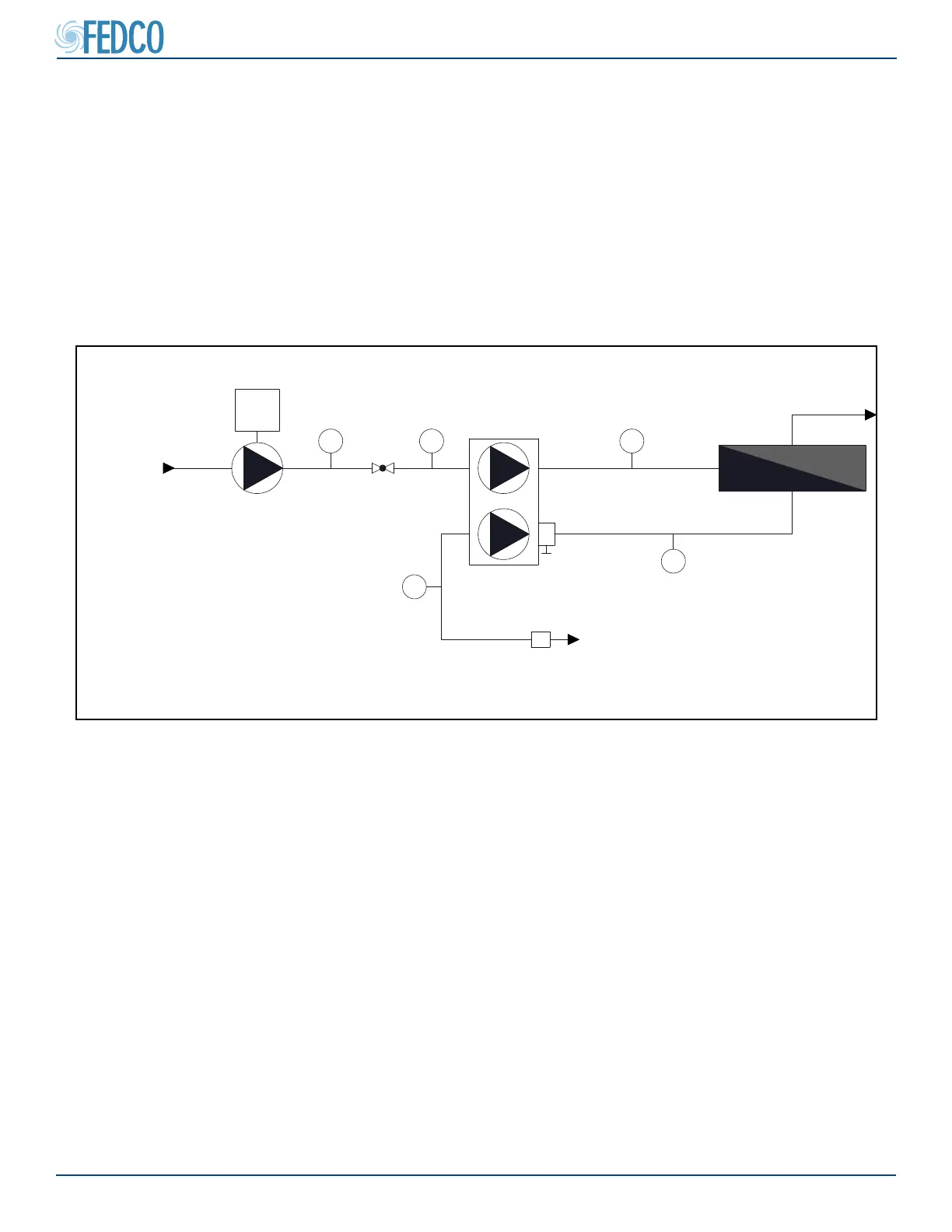
Figure 21 - Recommended Instrumentation
Motor
PG1
Brine
Permeate
Product
Feed Pump
Brine Outlet
(If Equipped)
Brine Stream
High Pressure
PG4
PG5
Throttle Valve
PG3
High Pressure
Feed
Pump To Inlet
PG2
High Pressure
Pre-Treatment
FM
HPB™
Flow Meter
(If Equipped)
Upstream Filtration
• The booster must be protected from debris in
the feed water such as sand, gravel, or other
particulate matter.
• A 20 micron lter must be installed upstream of
the feed pump inlet to protect against foreign
matter entering the system.
• Temporary strainers should be installed after
initial start up or repairs to protect the pump
from possible debris.
 Loading...