MSD
TM
Series
© Copyright 2018 Fluid Equipment Development Company | www.fedco-usa.com
- 18 -
Pump Assembly Continued
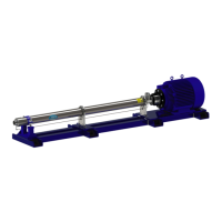
Figure 24 - Install Flex Coupling On Motor
Shaft
APPLY SYSTEM COMPLIANT
ANTI-SEIZE COMPOUND
Flexible Coupling Check
6. Apply a system compliant anti-seize com-
pound to the motor shaft keyway and install
the motor shaft key and coupling.
NOTES: If the motor shaft key does not t
properly in the coupling keyway, lightly le the
motor shaft key until a proper t is obtained.
Figure 23 - Coupling Guard Removal
5. Loosen screws and remove the two coupling
guards. This allows better access to view
the coupling alignment in later steps.
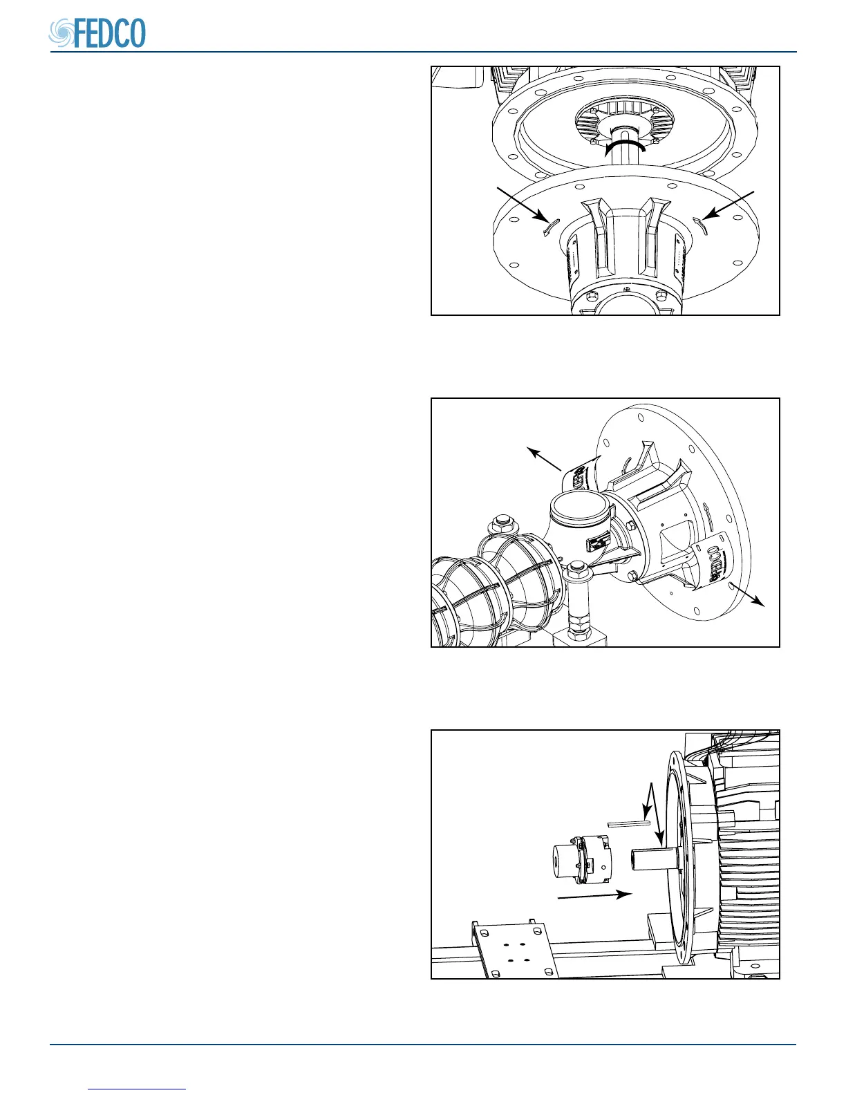
Figure 22 - Direction Arrows On Motor Adapter
3. Prior to pump installation energize the motor
to determine the direction of motor rotation.
The correct rotation is indicated by arrows
on the motor adapter. If the rotation is incor-
rect, reverse the polarity of motor wiring to
change the direction of rotation.
NOTES: Reversing polarity of the VFD power
input wires will not change the motor rotational
direction.
4. If the motor rotational direction is correct,
disconnect power to the motor according to
lock-out/tag-out procedures and complete
all electrical connections according to local
codes and regulations.