MSD
TM
Series
© Copyright 2018 Fluid Equipment Development Company | www.fedco-usa.com
- 45 -
Pump Assembly Continued
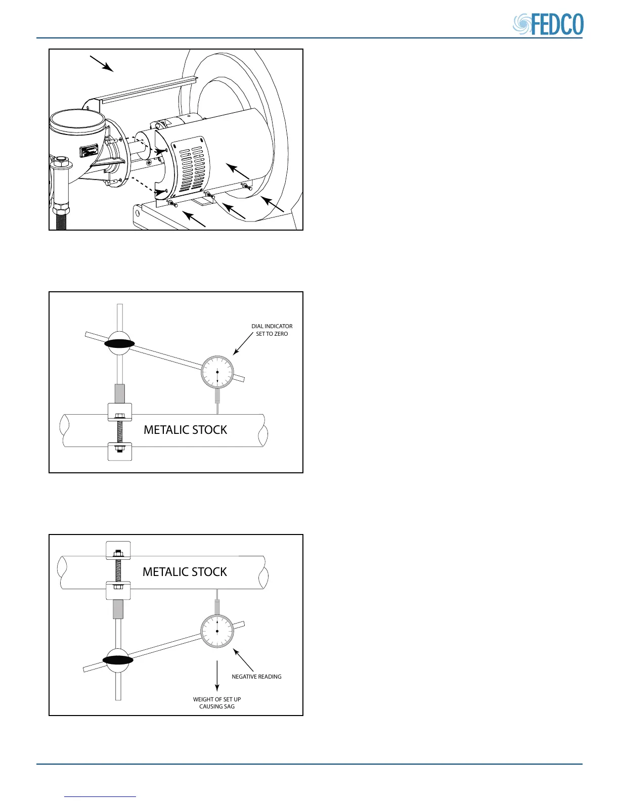
15. Install the sheet metal coupling guards.
16. Tighten mounting bolts to “Inlet Housing
Bolts” torque value found in the Fastener
Torque Specications section of this manu-
al.
Figure 85 - Sheet Metal Coupling Guard
Installation
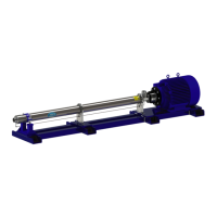
Sag Test
The Sag Test is used to measure the amount
of deection that a dial indicator bracket will un-
dergo at a given distance under its own weight.
This determines the sag tolerance of a given
dial indicator set up.
1. Assemble a dial indicator set up similar to
the one which will be used during the align-
ment procedure and place it on a length of
suitable metal stock. Set the indicator to
zero.
Figure 86 - Sag Test Dial Indicator Set Up
METALIC STOCK
DIAL INDICATOR
SET TO ZERO
Figure 87 - Recording Sag Test Negative
Indicator Reading
METALIC STOCK
NEGATIVE READING
WEIGHT OF SET UP
CAUSING SAG
2. Without disturbing the indicator set up, invert
the entire set up 180° (turn it upside down).
3. Record the amount of deection measured
on the indicator. It will read as a negative
number.