MSD
TM
Series
© Copyright 2018 Fluid Equipment Development Company | www.fedco-usa.com
- 49 -
Pump Assembly Continued
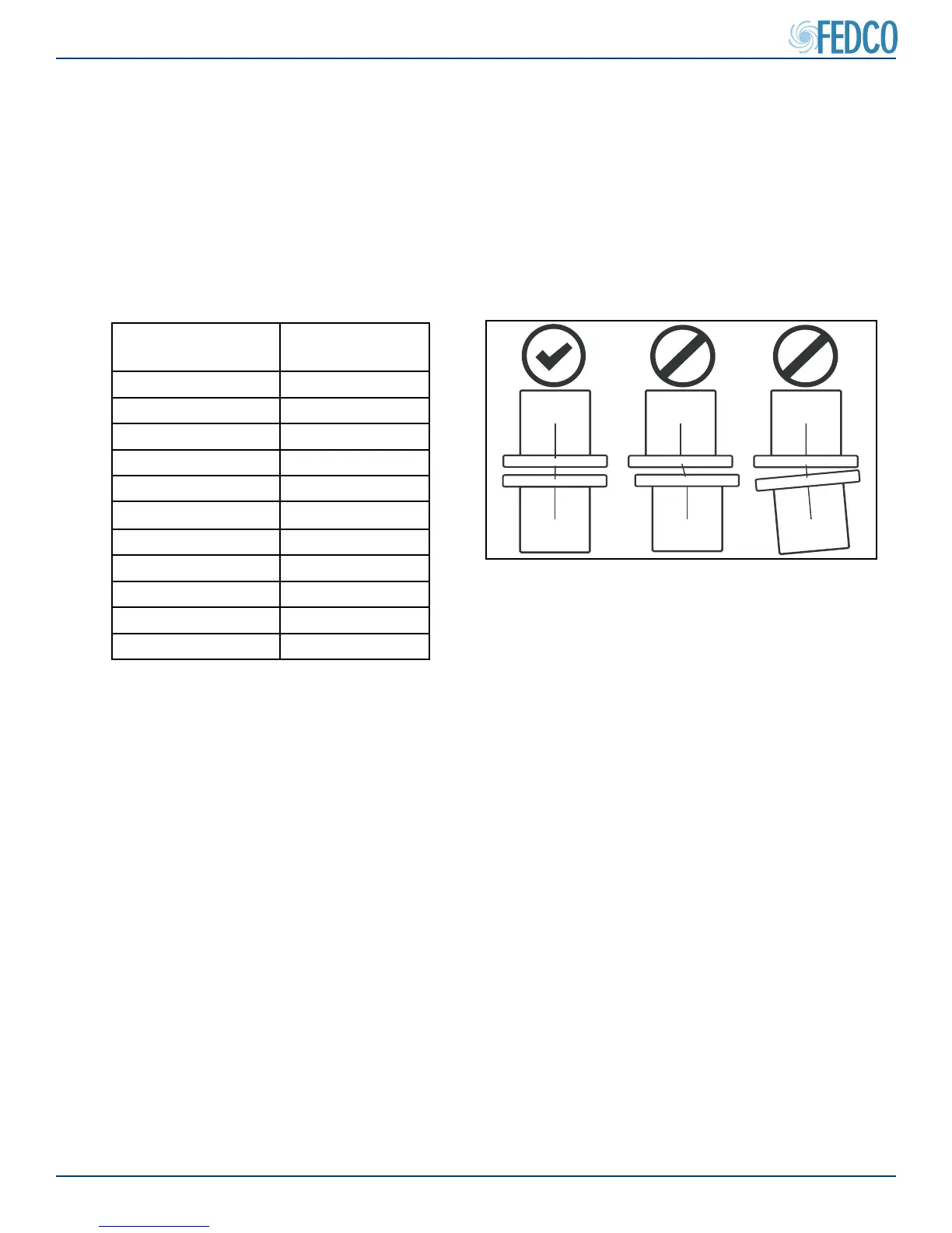
Flanged Connections
• Flange faces should be parallel 1/16 inch per foot diameter.
• Flange bolt holes should be aligned with a maximum oset of 1/8”
• Flange faces must be no more than a maximum of .5 degrees from each other.
• Take appropriate measures to compensate thermal expansion of the piping.
• Measure and record the ange gaps in the Start-Up Records section of this manual.
Flanges Pipe Size
(in.)
Allowable Gap
(in.)
½ 0.018
¾ 0.020
1 0.022
1 ½ 0.026
2 0.031
3 0.039
4 0.049
6 0.057
8 0.070
10 0.083
12 0.099
Figure 94 - Pipe Flange Fitting Allowable Gap
YES
NO
NO
Figure 95 - Proper Piping Alignment