601 Old Airport Road • Bristol, VA 24201 Phone (276) 669-4084 • FAX (276) 669-1869 • www.federalpacific.com • ISO9001:2015
SECTION IB-2A-210
INSTALLATION & OPERATION INSTRUCTIONS
TYPE PSE PAD-MOUNTED SWITCHGEAR
NOVEMBER 2017, REV 4.2
PAGE 12
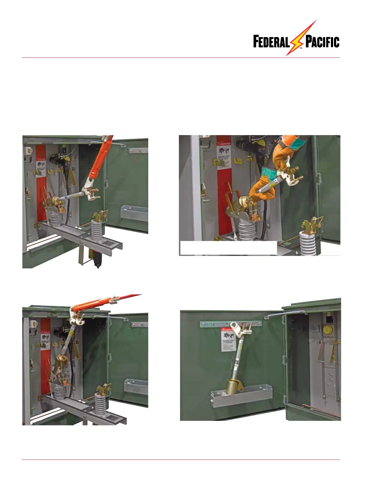
Figure 28. By pulling shotgun clamp stick upward, fuse
will unlatch.
Figure 29. Shotgun clamp stick secured to fuse pull ring
and fuse assembly being lifted from the latched position
and being removed from fuse hinge.
17. Lower the interlock lever.
18. If applicable, remove the insulating protective cover from the
bushing-well insert.
19. Move the elbow connector from the feed-through standoff
bushing onto the 200-ampere bushing well insert.
20. If applicable, remove the grounding elbow from the feed-through
standoff bushing.
21. Remove the feed-through standoff bushing.
22. Close and padlock the main door before leaving gear.
Figure 31. Fuse fully removed from fuse mounting and stored on optional
fuse storage hooks on door.
Figure 30. Alternate method using insulating-gloved hand, if user’s
standard operating procedures permit, to remove or install fuse assembly
of fuse mounting.
Internal contact and bushing well are
visible, fuse is totally isolated at both ends.