EasyManuals Logo

Feig Electronic OBID i-scan UHF User Manual

Feig Electronic OBID i-scan UHF
29 pages
To Next Page IconTo Next Page
To Previous Page IconTo Previous Page
Page #18 background imageLoading...
Page #18 background image
OBID
i-scan
®
UHF
Installation
ID ISC.LRU1002
FEIG ELECTRONIC GmbH
Page 18 of 29
M31010-1e-ID-B.docx
4.5.2.
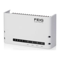
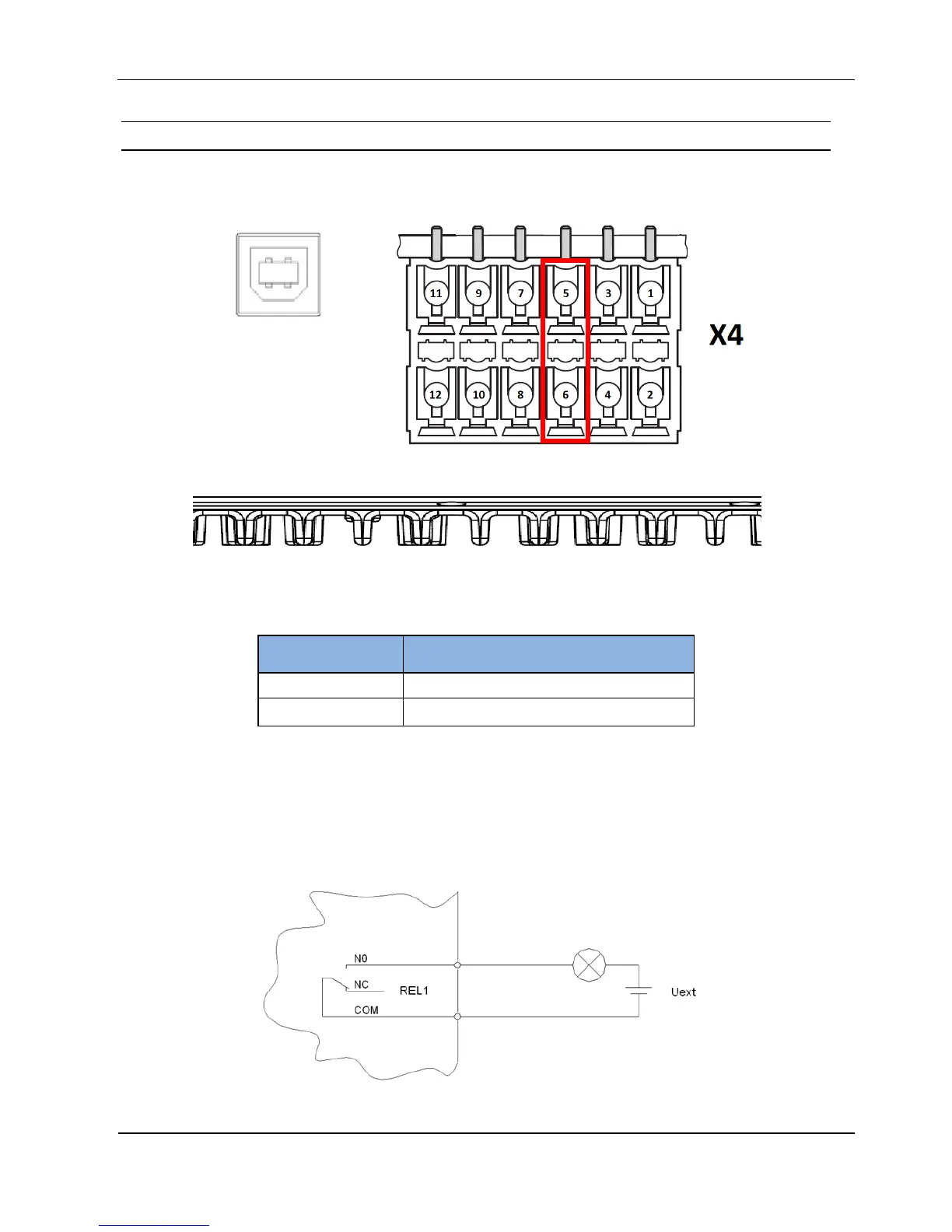
Relay output on connector X4
There is 1 relay output available on connector X4.
Figure 13: Relay output pin-outs REL1
Table 12: Pin Assignment Relay Output REL1
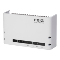
CAUTION:
The relay output is configured for max. 24 V DC / 2 A constant load.
The switching current must not exceed 1A.
The relay output is intended for switching resistive loads only. If an inductive load is con-
nected, the relay contacts must be protected by means of an external protection circuit.
Figure 14: Internal and possible external wiring of the relay output
Pin Number
at Connector X4
Pin Assignment
5
REL1-NO
6
REL1-COM

Questions and Answers:

Question and Answer IconNeed help?

Do you have a question about the Feig Electronic OBID i-scan UHF and is the answer not in the manual?

Feig Electronic OBID i-scan UHF Specifications

General IconGeneral
BrandFeig Electronic
ModelOBID i-scan UHF
CategoryCard Reader
LanguageEnglish

Related product manuals