Terminals
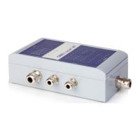
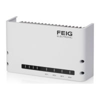
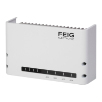
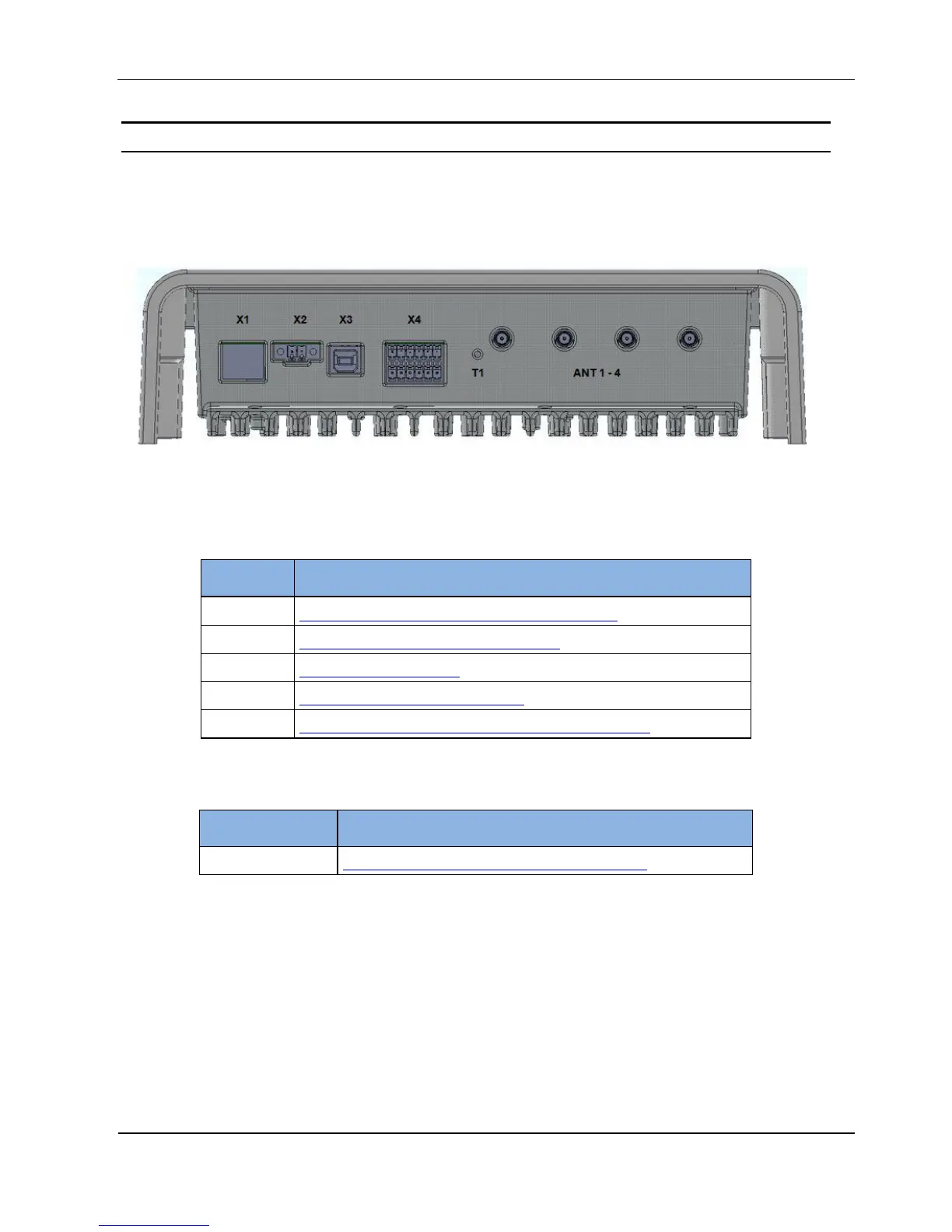
On the lower side of the reader housing the different cable connectors are positioned. Figure 2:
Connection Overview shows the arrangement of the connectors and Table 3: Connection terminals
shows which connection for the different cables are used. Table 4: Push button function shows the
available push buttons.
Figure 2: Connection Overview
Table 3: Connection terminals
Connection of the external antennas (Impedance 50)
10/100Tbase network connection with RJ-45
USB interface for host communication
Digital input, digital output, relay output and RS232 interface
Table 4: Push button function
Internal push button for complete configuration reset
 Loading...