S01-1.5)
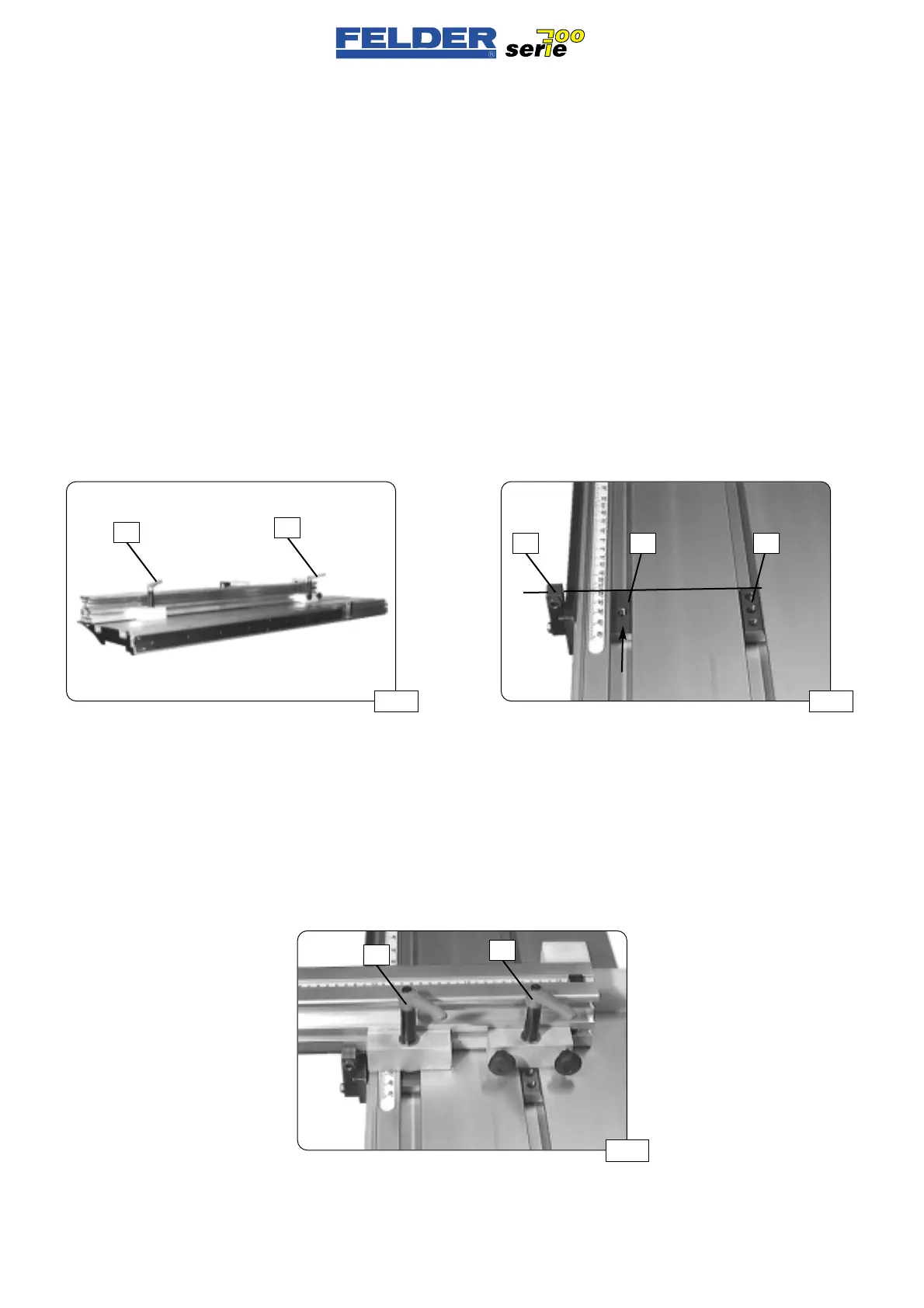
Montage Ablänganschlag
Der Ablänganschlag ist im Lieferzu-
stand am Schiebetisch festgeklemmt.
Siehe Abb. 14
Klemmhebel
K1 und K2 ganz lösen
und Anschlag entfernen.
Den losen Nutenstein
N1 aus der
rechten Nut ausfädeln und in die linke
hineinschieben.
Den Nutenstein
N1 soweit hineinschie-
ben, daß er in etwa auf einer Linie mit
dem Nutenstein
N und dem Anschlag
A liegt.
Siehe Abb. 15
Den Ablänganschlag mit den Klemm-
backen auf die Nutensteine setzen und
mit den Klemmhebeln
K1 und K2 fest-
klemmen.
Siehe Abb. 16
S01-1.5)
Assembly of cross-cutting stop
The cross-cutting stop is clamped to
the sliding table in at the time of deli-
very.
See fig. 14.
Completely release the clamping lever
K1 and K2 and remove the stop.
Remove the loose slot block
N1 from
the right groove and insert it into the
left one.
Insert the slot block
N1 to the point
that it is approximately aligned with
the slot block
N and the stop A.
See fig. 15.
Place the cross-cutting stop with clam-
ping jaws on the slot blocks and
clamp with the clamping levers
K1
and K2.
See fig. 16.
S01-1.5)
Montaggio guidapezzo longi-
tudinale
Alla fornitura, il guidapezzo longitudi-
nale è fissato alla tavola scorrevole.
Vedere fig. 14
Allentare completamente le leve di
serraggio
K1 e K2 e rimuovere il
guidapezzo.
Sfilare il tassello scorrevole allentato
N1 dalla scanalatura destra e inserirlo
in quella sinistra.
Spingere dentro il tassello scorrevole
N1 finché non si trovi approssimativa-
mente in linea con il tassello
N e la
battuta
A.
Vedere fig. 15
Mettere il guidapezzo longitudinale
con le ganasce sui tasselli scorrevoli e
fissarlo con le leve di serraggio
K1 e
K2.
Vedere fig. 16
- 8 -
S01 V2/2000 S1
Abb 15Abb 14
Abb 16
N1A
K1
K2
K1
K2
N
 Loading...

