S01-1.6)
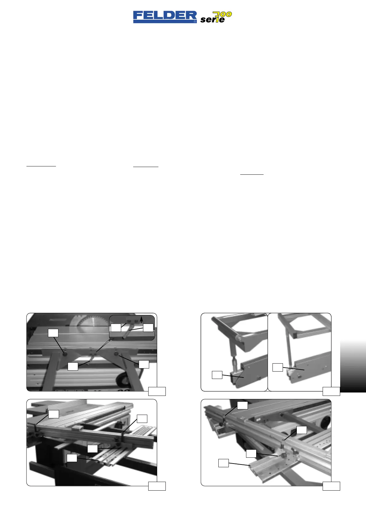
Montage Auslegertisch
Exzenterhebel E lösen und Ausleger-
tisch am Schiebetisch einhängen.
Siehe Abb. 18
Den Auslegerarm
A ausschwenken
und Auslegertisch am Auslegerarm
abstützen.
(Dazu Auslegertisch hinten anheben).
Siehe Abb. 19
Die Ausgleichsschrauben
L nur leicht
anziehen und den Auslegertisch ent-
lang des Schiebetisches mit dem
Klemmhebel
E in gewünschter Position
festklemmen. (Klemmplatte
P hinein-
schieben)
Achtung!
Die Ausgleichsschrauben L dienen nur
zum Spiel- bzw. Winkelausgleich!
Auf keinen Fall fest anziehen!
Der Ablänganschlag wird mit den bei-
den Klemmhebeln
K1 und K2 am Aus-
legertisch fixiert.
Siehe S. 14
Bei einem Auslegertisch mit Gradra-
sterung wird zuerst der Nutenstein
N
in die mittlere Nut der Auflageschiene
AL eingefädelt.
S01-1.6)
Assembly of bracket arm table
Release the cam lever E and engage
the bracket arm table on the sliding
table. See fig. 18.
Pivot the bracket arm
A out and sup-
port the bracket arm table on the
bracket arm. (lift the rear of the
bracket arm table for this purpose).
See fig. 19.
Tighten the compensating screws
L
only slightly and clamp the bracket
arm table in the desired position
along the sliding table with the clam-
ping lever
E. (insert clamping plate P)
Attention!
The compensating screws L serve to
adjust play and angles.
Do not tighten under any circum-
stances!
The cross-cutting stop is fixed on the
bracket arm table with the clamping
levers
K1 and K2.
See p. 14
For a bracket arm table with degree
indexing, insert the slot block
N in the
central groove of the supporting rail
AL.
S01-1.6)
Montaggio tavola di bandiera
Allentare la leva eccentrica E e
agganciare la tavola di bandiera alla
tavola scorrevole. Vedere fig. 18
Girare il braccio
A e sorreggere la
tavola di bandiera su di esso.
(Sollevare la tavola di badiera).
Vedere fig. 19
Stringere leggermente le viti di livella-
mento
L e fissare nella posizione
voluta la tavola di bandiera lungo la
tavola scorrevole mediante la leva di
serraggio
E. (inserire la piastra di
bloccaggio
P)
Attenzione!
Le viti di livellamento L servono solo
per bilanciare il gioco e la squadra
Non stringerle mai!
Il guidapezzo longitudinale viene fis-
sato con le due leve di serraggio
K1 e
K2 sulla tavola di bandiera.
Vedere pag. 14
In una tavola di supporto con arresto
graduale viene prima infilato il tassel-
lo scorrevole
N nella scanalatura cen-
trale della guida di sostegno
AL.
- 9 -
S01 V2/2000 S1
S01
Abb 20Abb 19
Abb 17
P E
E
L
L
K2
K1
K2
K1
AL
N
AL
N
Abb 18
A
A
 Loading...

