- 10 -
S01 V2/2000 S1
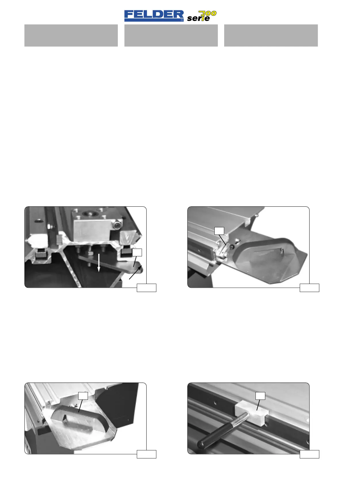
Abb 22A Abb 22B
G S
Abb 21A
H
Abb 21B
H1
S01-2)
Bedienung der Schiebetisch-
einheit
S01-2.1)
Arretiereinrichtung
Der Schiebetisch kann in mehreren
Positionen arretiert werden.
Dies ist z.B. für Fräsarbeiten oder
Längsschnitte mit dem Kreissägean-
schlag notwendig.
Je nach Ausstattung der Maschine ist
der Schiebetisch mit einem Arretierbol-
zen oder einer Arretiereinrichtung
(Version X, XL) ausgerüstet.
Arretierung lösen:
Arretierhebel
H nach unten drücken
und nach rechts drehen bis er am Pro-
fil ansteht.
Siehe Abb. 21
Bei den Versionen X und XL den Hebel
H1 anheben.
Siehe Abb. 21B
S01-2.2)
Schiebegriff
Zum Verschieben und Zurückziehen
des Schiebetisches wird der Schiebe-
griff
G oder der Ablänganschlag ver-
wendet.
Zusätzlich kann einSeitenhandhebel
S
verwendet werden, der an der Stahl-
schiene in jeder beliebigen Position
geklemmt werden kann.
Siehe FELDER Zubehörkatalog
S01-2)
Operation of sliding table
assembly
S01-2.1)
Blocking mechanism
The sliding table can be blocked in
several positions.
This is necessary e.g. for shaping
work or ripping with the tablesaw
fence.
Depending on the version of the
machine, the sliding table is equipped
with a retaining bolt or retaining unit
(version X, XL).
Releasing retainer:
Press locking lever
H downward and
turn right until it is positioned at the
profile.
Refer to fig. 21A
For the versions X and XL, lift the lever
H1.
Refer to fig. 21B
S01-2.2
Hand grip
Use the sliding grip G or the cross-cut-
ting stop to shift and retract the sliding
table.
In addition, a lateral hand lever
S can
be used that can be clamped in any
required position.
See the FELDER accessory catalog.
S01-2)
Comando gruppo tavola scor-
revole
S01-2.1)
Dispositivo di bloccaggio
La tavola scorrevole può essere bloc-
cata in diverse posizioni.
Questo è necessario per es. per opera-
zioni di fresatura o tagli longitudinali
con guidapezzo per sega circolare.
A seconda dell’equipaggiamento in
dotazione alla macchina, la tavola
scorrevole è provvista di un perno di
arresto o un dispositivo di arresto (ver-
sione X, XL).
Per allentare l’arresto:
Spingere verso il basso la leva di arre-
sto
H e ruotare verso destra finché
non si trovi sul profilo.
Vedere fig. 21A
Nelle versioni X e XL sollevare la leva
H1. Vedere fig. 21B
S01-2.2)
Maniglia scorrevole
Per spostare avanti e indietro la tavola
scorrevole viene utilizzata la maniglia
scorrevole
G o il guidapezzo longitu-
dinale.
Inoltre può essere utilizzata una leva
laterale
S che può essere fissata in
qualsiasi posizione sulla guida
d’acciaio.
Vedere catalogo accessori FELDER
 Loading...

