S01-3)
Bedienung Ablänganschlag
S01-3.1)
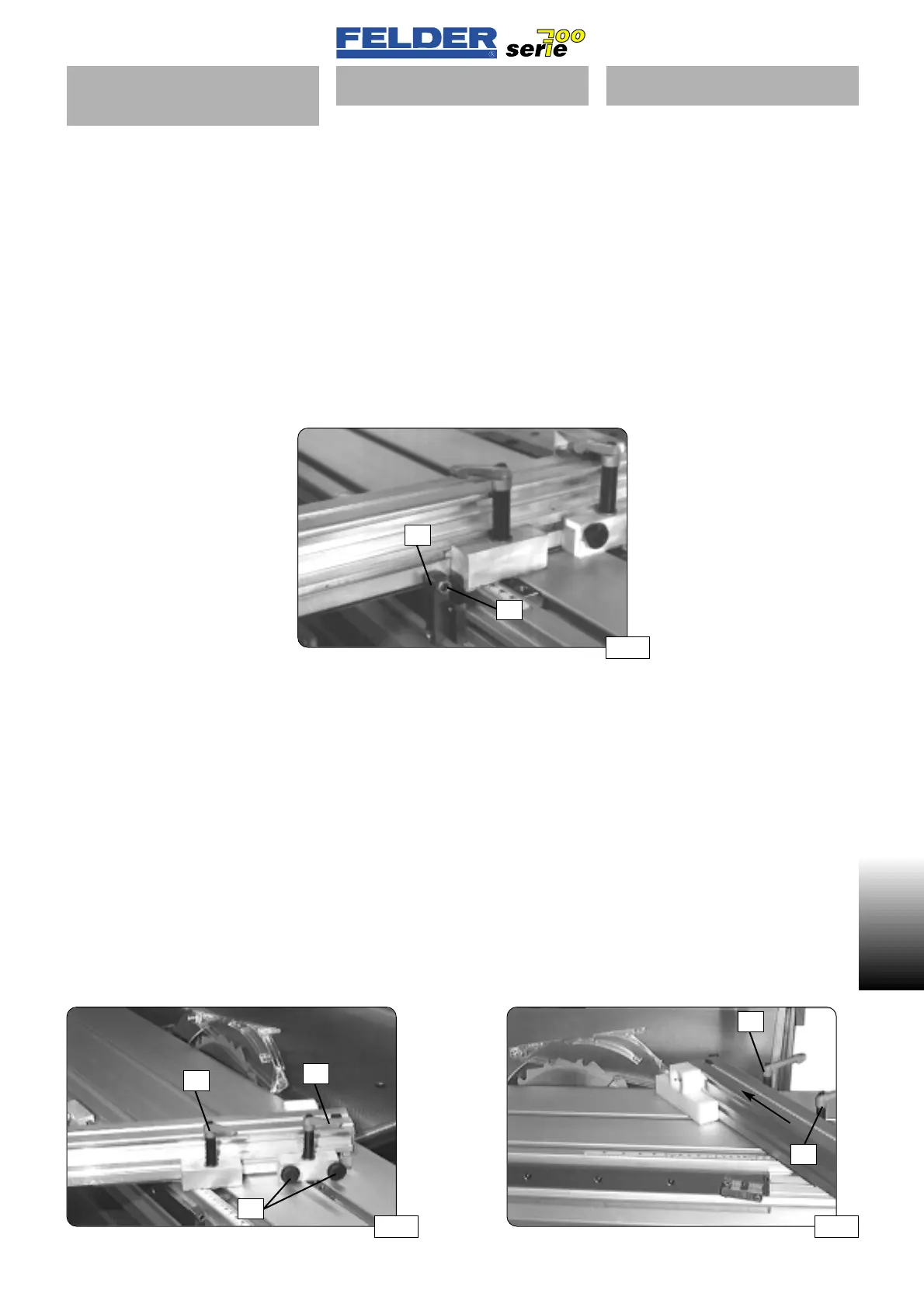
90°- Endanschlagklappe
Der Ablänganschlag ist von -45° bis
+45° schwenkbar und hat bei 0° (90°)
eine Anschlagklappe
K um diese Posi-
tion schnell einstellen zu können.
Der 90°- Winkel kann zudem an die-
ser Klappe feineingestellt werden.
(Schraube
S)
Beim Schwenken des Anschlages auf
Gehrung wird die Endanschlagklappe
nach unten weggeklappt.
Siehe Abb. 23
S01-3.2)
Gehrungsanschlag
Klemmhebel K1 und K2 öffnen und
Ablänganschlag auf gewünschten
Winkel schwenken.
Die Rändelschrauben
R lösen und den
Anschlag in Richtung Kreissägeblatt
verschieben, um die Anschlagfläche
möglichst nahe am Kreissägeblatt zu
haben.
Den Anschlag mit den Klemmhebeln
K1 und K2 klemmen.
Siehe Abb. 24 / 25
S01-3)
Operation of cross-cutting stop
S01-3.1)
90° retractable stop
The cross-cutting stop can be pivoted
from -45° to +45° and has a retracta-
ble stop
K at 0° (90°) in order to find
this position quickly.
A fine adjustment of the 90° angle
can also be performed here.
(screw
S)
The retractable stop can be folded
away downwards when pivoting the
stop to the mitre position.
Refer to fig. 23
S01-3.2)
Mitre fence
Open clamping levers K1 and K2 and
pivot the cross-cutting stop to the desi-
red angle.
Release the thumbscrews
R and move
the stop toward the circular saw blade
so that the stop surface is as close to
the blade as possible.
Clamp the stop with the clamping
levers
K1 and K2.
See fig. 24 / 25
S01-3)
Comando guidapezzo longitu-
dinale
S01-3.1)
Deflettore finecorsa 90°
Il guidapezzo longitudinale può essere
ruotato da -45° a +45°, e a 0° (90°)
ha un deflettore di arresto
K che serve
a regolare velocemente questa posi-
zione.
Inoltre la regolazione di precisione
dell’angolo di 90° può essere fatta su
questo deflettore.
(vite
S)
Ruotando il guidapezzo sullo smusso
il deflettore di fine corsa viene ribalta-
to verso il basso.
Vedere fig. 23B
S01-3.2)
Guidapezzo smusso
Aprire le leve di serraggio K1 e K2 e
ruotare il guidapezzo longitudinale
sull’angolo voluto.
Allentare le viti a testa zigrinata
R e
spostare il guidapezzo in direzione
della lama della sega circolare per
avvicinare il più possibile la superficie
di battuta alla lama.
Fissare il guidapezzo con le leve di
serraggio
K1 e K2.
Vedere figg. 24 / 25
- 11 -
S01 V2/2000 S1
S01
Abb 23
Abb 25Abb 24
K
K1
K1
K2
K2
R
S
 Loading...

