- 13 -
S01 V2/2000 S1
S01
Abb 29Abb 28
G
S
L
S01-3.5)
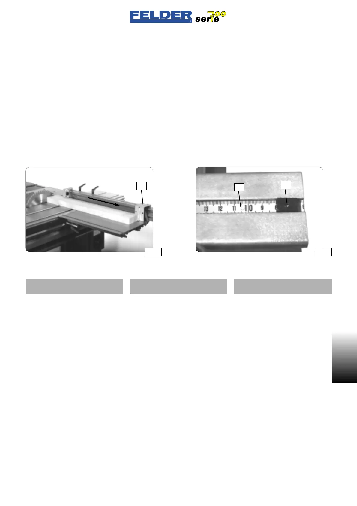
Setting the cross-cutting scale
The cross-cutting scale may require
fine adjustment depending on the saw
blade used (thickness of saw blade).
Pivot the cross-cutting stop to 90° and
move to the rearmost position. Refer to
fig. 28
Cut a test workpiece and measure it
exactly.
The measured value must be visible in
the lens
L.
To correct the value, release the stud
G and move the scale S.
Refer to fig. 29
S01-4)
Operating the bracket arm table
You can use the bracket-arm table at
the leading or trailing edge of the
workpiece.
Thus you can mount the fence at the
leading or trailing edge of the
bracket-arm table.
The advantage of mounting the
bracket-arm table at the leading edge
of the workpiece is to obtain a longer
length of cut.
Also see
S01-1.1)
Cutting lengths
S01-3.5)
Regolazione scala longitudinale
La regolazione della scala longitudi-
nale dev’essere effettuata a seconda
della lama utilizzata (spessore lama
sega).
A tal fine ruotare il guidapezzo longi-
tudinale di 90° e portarlo nella posi-
zione più arretrata. Vedere fig. 28
Tagliare un pezzo di prova e misurar-
lo esattamente.
Il valore misurato dev’essere visibile
nella lente d’ingrandimento
L.
Per correggere allentare la vite di
arresto
G e spostare la scala S.
Vedere fig. 29
S01-4)
Comando tavola di bandiera
La tavola di bandiera può essere utili-
zzata dal lato di spinta in avanti o
indietro.
Quindi l’arresto sulla tavola di sup-
porto può essere spostato dal lato di
spinta in avanti a quello di spinta
indietro.
Il montaggio della tavola di supporto
sul lato di spinta in avanti ha come
vantaggio una maggiore lunghezza di
taglio.
Vedere anche
S01-1.1)
Lunghezze di taglio
S01-3.5)
Einstellen der Ablängskala
Je nach verwendetem Sägeblatt (Säge-
blattstärke) muß die Ablängskala fein-
eingestellt werden.
Den Ablänganschlag dazu auf 90°
schwenken und in die hinterste Position
bringen. Siehe Abb. 28
Ein Probewerkstück abschneiden und
genau abmessen.
Der gemessene Wert muß in der Lupe
L ersichtlich sein.
Zur Korrektur den Gewindestift
G lösen
und die Skala
S verschieben.
Siehe Abb. 29
S01-4)
Bedienung Auslegertisch
Der Auslegertisch kann stoß- oder
schubseitig verwendet werden.
Der Anschlag kann daher am Ausle-
gertisch von der Stoß- auf die Schub-
seite umgesetzt werden.
Der Vorteil der stoßseitigen Montage
des Auslegertisches ist eine größere
Schnittlänge.
Siehe auch
S01-1.1)
Schnittlängen
 Loading...

