- 14 -
S01 V2/2000 S1
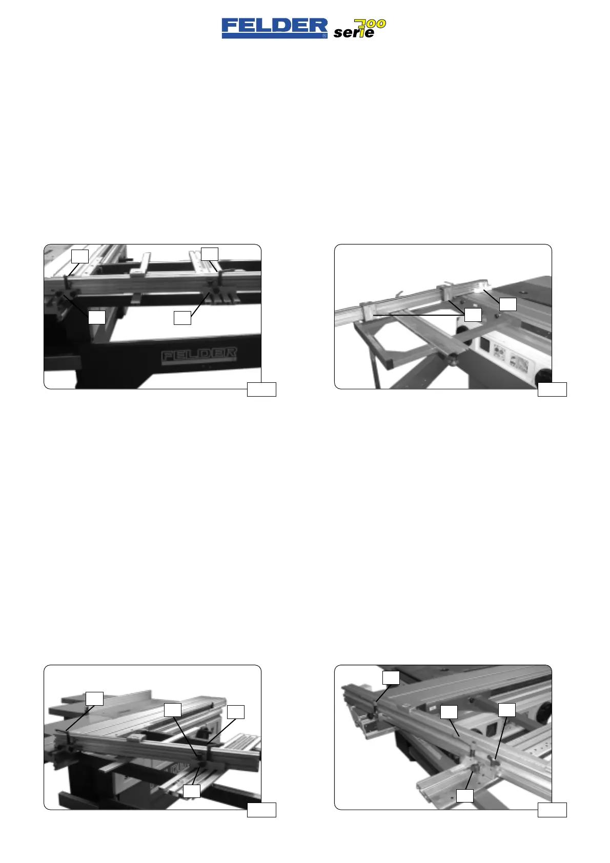
Abb 32 Abb 33
K1
K1
K2 K2
S
S
B B
S01-4.1)
The cross-cutting stop on the
bracket arm table
To change the stop from the leading to
the trailing edge or vice versa, remove
both clamping levers
K1 and K2
remove the stop.
Now position the lateral stops
Q, both
clamping blocks
B and D and the split-
ter tongue
S on the other side of the
stop.
Install the stop on the other side of the
bracket-arm table.
S01-4.2)
Degree indexing option
Release the clamping levers K1 and
K2.
Release the play compensating screw
S and pull indexing bolt B upwards.
With the indexing bolt
B, index the
stop at the desired angle and tighten
the play compensating screws
S as
well as the clamping levers
K1 and
K2.
Refer to fig. 32
The stop may also be clamped in any
intermediate position.
S01-4.1)
Guidapezzo longitudinale sulla
tavola di bandiera
Per trasformare il guidapezzo dal lato
di spinta in avanti a quello di spinta
indietro o viceversa svitare completa-
mente le leve di serraggio
K1 e K2 e
rimuoverle dal guidapezzo.
Spostare il/i guidapezzo/i trasversa-
le/i
Q e le due ganasce B e D nonché
la linguetta antischegge
S sull’altro
lato di arresto.
Ora montare il guidapezzo sull’altro
lato della tavola di bandiera.
S01-4.2)
Opzione arresto graduale
Allentare le leve di serraggio K1 e K2
Allentare la vite di compensazione
gioco
S e tirare verso l’alto il perno di
arresto
B.
Inserire il guidapezzo nell’angolo
voluto tramite il perno di arresto
B e
tirare le viti di compensazione gioco
S
nonché le leve di serraggio K1 e K2.
Vedere fig. 32
Naturalmente il guidapezzo può esse-
re fissato in ogni posizione interme-
dia.
S01-4.1)
Der Ablänganschlag am
Auslegertisch
Zum Umsetzen des Anschlages von
Stoß- auf Schubseite oder umgekehrt
die Klemmhebel
K1 und K2 ganz her-
ausdrehen und Anschlag entfernen.
Den / die Queranschläge
Q und
beide Klemmbacken
B und D sowie
die Splitterzunge
S auf die andere
Anschlagseite umsetzten.
Den Anschlag nun auf der anderen
Auslegertischseite montieren.
S01-4.2)
Option Gradrasterung
Klemmhebel K1 und K2 lösen
Spielausgleichsschraube
S lösen und
Rastbolzen
B nach oben ziehen.
Anschlag mittels Rastbolzen
B in dem
gewünschten Winkel einrasten und
Spielausgleichsschrauben
S sowie
Klemmhebel
K1 und K2 anziehen.
Siehe Abb. 32
Der Anschlag kann natürlich auch in
jeder gewünschten Zwischengradstel-
lung geklemmt werden.
Abb 31Abb 30
K1
K1
S
Q
D
B
 Loading...

