A01-2)
Comando
A01-2.1)
Dispositivi di protezione
• Protezione albero pialla
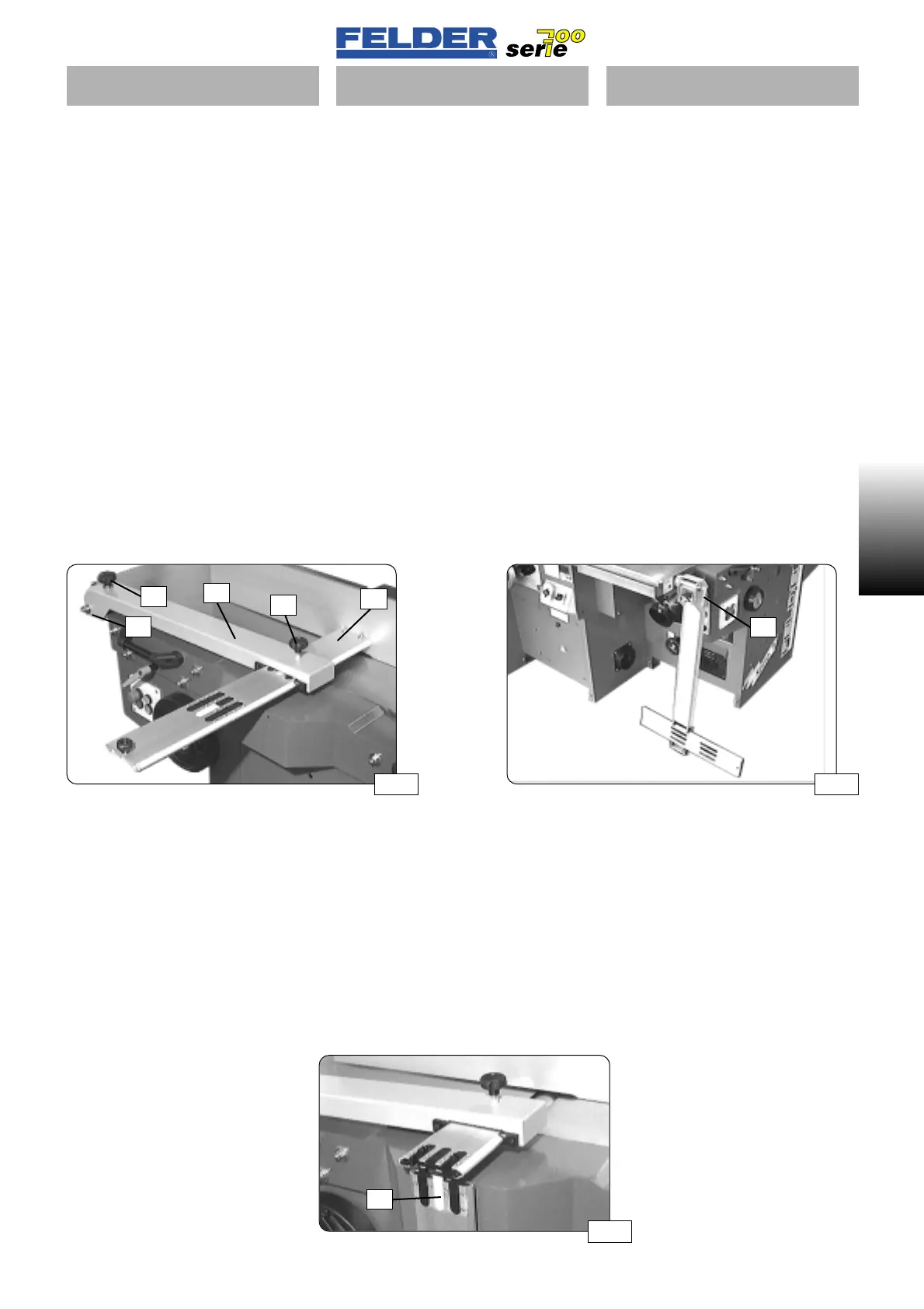
Vedere fig. 01
La protezione albero pialla consiste in
una barra di protezione S e in un
braccio di protezione A per il ponte
della pialla a filo.
La barra di protezione può essere
regolata continuamente in altezza e
larghezza.
Regolazione in altezza: vite di regola-
zione H
Regolazione in larghezza: vite di ser-
raggio B
Nei modelli combinati tutta la prote-
zione del ponte pialla a filo può
essere ribaltata dopo aver aperto la
leva di serraggio K.
In tal modo si può utilizzare tutta la
superficie di appoggio dei banchi di
lavoro.
• Protezione confort albero pialla
La protezione confort é dodata di due
giunture. La tiri verso di sé
alcuni mm oltre il spigolo della
macchina e allento il tasto G, cosÌ
é possibile estrarre dalla chiusura la
stecca, inclinandola verso il
basso.
A01-2)
Bedienung
A01-2.1)
Schutzeinrichtungen
• Abricht- Brückenschutz
Siehe Abb. 01
Der Abricht- Brückenschutz besteht
aus der Schutzschiene S und dem
Abricht- Brückenschutz- Arm A.
Die Schutzschiene ist stufenlos in der
Höhe und in der Breite verstellbar.
Höhenverstellung: Stellschraube H
Breitenverstellung: Klemmschraube B
Bei Kombimodellen kann der ganze
Abricht- Brückenschutz nach öffnen
des Klemmhebels K abgeklappt wer-
den.
Somit wird die gesamte Auflagefläche
der Abrichttische nutzbar.
• Abklappen der Schutzschiene
Als Option kann die Maschine mit
einer abklappbaren Schutzschiene
ausgestattet sein. Ziehen Sie die
Schutzschiene soweit heraus daß der
Abklapppunkt einige mm vor der
Maschinenkante ist.
Drücken Sie die Entriegelungstaste G.
Ziehen Sie den vorderen Teil der
Schutzschiene heraus und klappen Sie
ihn nach unten ab.
- 5 -
A01 V1/99 S1
A01
Abb 01
Abb 03
S
A
H
B
G
K
Abb 02
K
A01-2)
Operation
A01-2.1)
Protective devices
• Joiner bridge guard
See fig. 01
The joiner bridge guard consists of the
protective rail S and the joiner bridge
guard arm A.
The height and width of the protective
rail is continuously adjustable.
Height adjustment: set screw H
Width adjustment: clamping screw B
In combination models, the entire joi-
ner bridge guard can be removed
after opening the clamping lever K.
The entire surface area of the joiner
table is thus usable.
• Tilting down the protective bar
The machine can be optionally equip-
ped with a tiltable protective bar. Pull
the protective bar out far enough that
the tilting hinge is several mm over the
machine edge.
Press the release button G, pull out the
front part of the protective bar and tilt
it downward.
 Loading...

