A01-2.3)
Regolazione del giunto
(piano di lavoro per prelievo)
E’ necessaria quando vengono poste
speciali esigenze riguardo a un giunto.
Tavolo d`uscita sotto il livello della cir-
conferenza del coltello rotante
-> connettitura concava
Tavolo d`uscita sopra il livello della
circonferenza del coltello rotante
-> connettituta convessa
Tavolo d`uscita a livello della circonfe-
renza del coltello rotante
-> connettitura dritta.
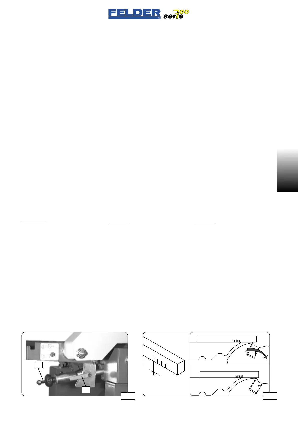
Allentata la manigliadel fissaggio K il
piano puo essere ragolato in altezza
con la maniglia S. 1 giro=0,20mm
Per abbassare il piano bisogna allen-
tare con alcuni giri la maniglia S poi,
girando il manico S il piano si muove
verso il basso.
La regolazione del piano va sempre
fatto dal basso in alto.
Attenzione:
Il tavolo d`uscita della piallatrice a filo
è regolato già in fabbrica e non deve
essere più toccato.
Regolazione di fabbrica del giunto:
Con un pezzo lungo 2 m risulta un
giunto cavo di 0,2-0,5mm. (regola-
zione standard)
Per il controllo preparare un calibro
come da fig. 07
Mettere questo calibro con “0” sul
bordo del piano di lavoro per prelievo
e ruotare a mano l’albero della pialla.
La lama della pialla deve trascinare
con sé il calibro di 2-3 mm (regola-
zione di fabbrica).
- 7 -
A01 V1/99 S1
A01
A01-2.3)
Einstellen der Fuge
(abnehmender Abrichttisch)
Dies ist notwendig wenn Sie spezielle
Anforderungen an eine Fuge stellen.
Abnahmetisch unter Messerflugkreis
-> Hohlfuge
Abnahmetisch über Messerflugkreis
-> Spitzfuge
Abnahmetisch auf Messerflugkreis
-> gerade Fuge
Nach Öffnen der Klemmschraube K
kann der Tisch durch rechtsdrehen der
Einstellschraube S nach oben verstellt
werden. 1 U=0,2mm
Zum Tieferstellen des Tisches wird die
Einstellschraube S zuerst einige
Umdrehungen herausgedreht und
dann wird der Tisch durch Hinunter-
drücken der Einstellschraube S nach
unten verstellt.
Die Einstellung des Tisches muß immer
von unten nach oben erfolgen.
Achtung:
Der abnehmende Abrichttisch ist
werkseitig eingestellt und sollte norma-
lerweise nicht mehr verstellt werden.
Werkseitige Fugeneinstellung:
Bei einer Werkstücklänge von 2m
ergibt sich eine Hohlfuge von 0,2-
0,5mm. (Übliche Einstellung)
Fertigen Sie zur Kontrolle eine Lehre lt.
Abb. 07
Diese Lehre bei ”0” an die Kante des
abnehmenden Abrichttische setzten
und die Hobelwelle händisch drehen.
Das Hobelmesser soll die Lehre 2-
3mm mitnehmen (Werkseinstellung).
A01-2.3)
Setting the join
(receiving joiner table)
This is necessary if you have special
requirements with regard to a join.
Joiner table below the circle of cut
-> concave joint.
Joiner table below the circle of cut
-> convex joint.
Joiner table heigh at the circle of cut
-> straight joint.
After opening clamp screw K, you can
raise the table by turning the setscrew
S to the right. 1 rev.=0.2mm
To lower the table, first loosen set-
screw S several turns, then lower the
table by pressing down setscrew S.
The table must always be set from
lower to higher.
Attention:
The receiving joiner table is factory set
and normally should not be adjusted.
The table is factory set so that along a
joint length of 2m a hollow joint of 0.2
to 0.5 mm is formed.
To check, make a gauge as per Fig.
07.
Place this gauge at “0” on the edge of
the receiving joiner table and turn the
planer arbor by hand.
The planer blade should move the
gauge 2 to 3 mm (factory setting).
Abb 06
K
S
 Loading...

