A01-2.8)
Operating the drilling unit
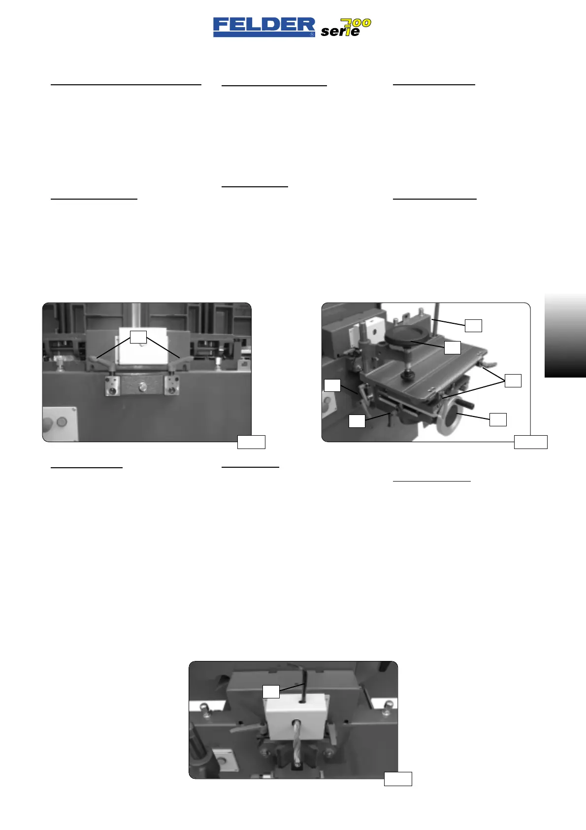
• Coupling and decoupling
See fig. 13
- Fix the drilling table in the rearmost
middle position.
- Engage the drilling support with the
locating pin in the coupling and lock
with the clamping levers KL.
• Operating parts
See fig. 13A
- Height adjustment H
- Adjusting lever V
- Drilling depth stop T
- Drilling length stop L
- Rotating hold-down D
- Height clamp K
• Inserting drills
See fig. 14.
- The 2-jaw drill chuck can be opened
and closed with a hexagon socket
wrench T (8 mm).
(minimum tightening torque: 20 Nm)
- Clamp the drilling tool using the ent-
ire available length of the drill
chuck.
Attention:
Remove the drilling tool immediately
after each drilling job!
-> Danger of injury!
A01-2.8)
Comando del cavatrice
• Accoppiamento e disaccoppiamento
Vedere fig. 13
- Fissare il banco di foratura in cen-
tro, nella posizione più arretrata.
- Agganciare il supporto di foratura
con il perno di inserzione nel dis-
positivo di accoppiamento e fissarlo
con le leve di serraggio KL.
• Elementi di comando
Vedere fig. 13A
- Regolazione in altezza H
- Leva di regolazione V
- Limitazione profondità di foratura T
- Limitazione lunghezza di foratura L
- Pressalegno girevole D
- Bloccaggio in altezza K
• Bloccaggio punta
Vedere fig. 14
- La mandrino bimorapinza viene
aperta e bloccata con una chiave
per viti a brugola T (8mm).
(Coppia minima di serraggio 20Nm)
- Stringere l’utensile perforatore per
tutta la lunghezza della mandrino.
Attenzione!
Rimuovere l’utensile perforatore subito
dopo l’operazione di foratura.
-> Pericolo di lesioni!
- 11 -
A01 V1/99 S1
A01
A01-2.8)
Bedienung der Bohreinheit
• An- und Abkoppeln
Siehe Abb. 13
- Bohrtisch in der hintersten, mittleren
Stellung fixieren.
- Bohrsupport mit den Aufnahmebol-
zen in die Koppeleinrichtung ein-
hängen und mit den Klemmhebeln
KL fixieren.
• Bedienungselemente
Siehe Abb. 13A
-Höhenverstellung H
- Verstellhebel V
- Bohrtiefenbegrenzung T
- Bohrlängenbegrenzung L
- Drehniederhalter D
-Höhenklemmung K
• Bohrer einspannen
Siehe Abb. 14
- Das Zweibackenbohrfutter wird mit
einem Inbusschlüssel T (8mm) geöff-
net und geklemmt.
(Mindestanzugsmoment 20Nm)
- Bohrwerkzeug über die ganze
Länge des Bohrfutters einspannen.
Achtung:
Bohrwerkzeug sofort nach jeder Bohr-
arbeit entfernen !
-> Verletzungsgefahr!
Abb 13 Abb 13A
Abb 14
KL
V
H
D
K
L
T
T
 Loading...

