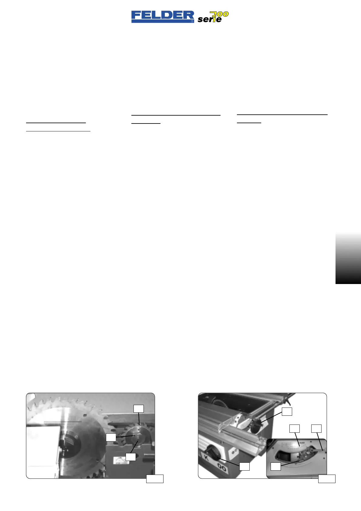
•Slitter blade
See fig. 04, 05, 07
Switch off main switch.
Move the sliding table all the way for-
ward and open the sliding cover D.
Hold the flange F (open-ended wrench
22 mm) and release the clamping
screw K (hexagon socket wrench
6 mm).
Only on machines with ”industrial”
slitting unit:
Turn blade lock S to the left.
This permits the use of a 250 mm
main saw blade and a 100 mm slit-
ting blade.
Place a new slitting blade V on the
shaft.
It is assembled out of the two saw hal-
ves and spacers and should be 0.1 to
0.2 mm wider than the main saw
blade.
Suitable slitting blades:
80mm dia. for slitting unit ”standard”
100mm dia. for slitting unit ”industrial”
Mount flange F and lock with clam-
ping screw K.
(minimum tightening torque: 20 Nm)
K01-2.4)
Adjusting the saw blade
See fig. 08
Cutting angle: handwheel H1
Cutting height: handwheel H2
Set the cutting height only as high as
necessary.
Read out on scale S
Clamp with clamping lever K1 and K2
•Lama incisore
Vedere figg. 04, 05, 07
Disinserire l’interruttore principale.
Spostare completamente in avanti la
tavola scorrevole e aprire il coperchio
scorrevole D.
Tenere ferma la flangia F (chiave fissa
da 22 mm) e allentare la vite di ser-
raggio K (chiave per vite a brugola da
6 mm).
Solo per macchine con
raschiatrice “industriale”:
Girare a sinistra il blocco lama S.
In tal modo si può usare la lama sega
principale da 250 mm nonché quella
della incisore da 100 mm.
Inserire la nuova lama per raschiatrice
V sull’asse.
Essa viene composta dalle due metà
della sega e dallo spessore e dovreb-
be essere più larga di 0,1 - 0,2 mm
rispetto alla lama sega principale.
Lame raschiatrice adatte:
ø80mm con incisore ”standard”
ø100mm con incisore ”industriale”
Sistemare la flangia F e fissarla con la
vite di serraggio K.
(Coppia minima di serraggio 20Nm)
K01-2.4)
Regolazione lama sega circo-
lare
Vedere fig. 08
Angolo di taglio: volantino H1
Altezza di taglio: volantino H2
Regolare l’altezza di taglio come da
necessità.
Lettura sulla scala S
Bloccaggio con leve di serraggio
K1 e K2
K01
•Vorritzblatt
Siehe Abb. 04, 05, 07
Hauptschalter ausschalten.
Den Schiebetisch ganz nach vorne
schieben und den Schiebedeckel D
aufschieben.
Flansch F festhalten (Gabelschlüssel
22 mm) und Klemmschraube K lösen
(Inbusschlüssel 6 mm).
Nur bei Maschinen mit ”Industrie”-
Vorritzer:
Blattsperre S nach links drehen.
Dadurch wir der Einsatz von 250 mm
Hauptsägeblatt sowie 100 mm Vor-
ritzsägeblatt ermöglicht.
Neues Vorritzblatt V auf die Welle
aufstecken.
Es wird aus den beiden Sägehälften
und den Distanzscheiben zusammen-
gesetzt und sollte 0,1 - 0,2 mm breiter
sein als das Hauptsägeblatt.
Geeignete Vorritzblätter:
ø80 mm bei Standard- Vorritzer
ø100 mm bei Industrie- Vorritzer
Flansch F aufsetzen und mit Klemm-
schraube K festklemmen.
(Mindestanzugsmoment 20 Nm)
K01-2.4)
Einstellen Kreissägeblatt
Siehe Abb. 08
Schnittwinkel: Handrad H1
Schnitthöhe: Handrad H2
Die Schnitthöhe nur so hoch einstellen
wie notwendig.
Ablesen auf Skala S
Klemmen mit Klemmhebel K1 und K2
Abb 07 Abb 08
- 7 -
K01 V1/99 S1
H1
H2
K2S
K1
F
V
K
 Loading...

