F01-2.2)
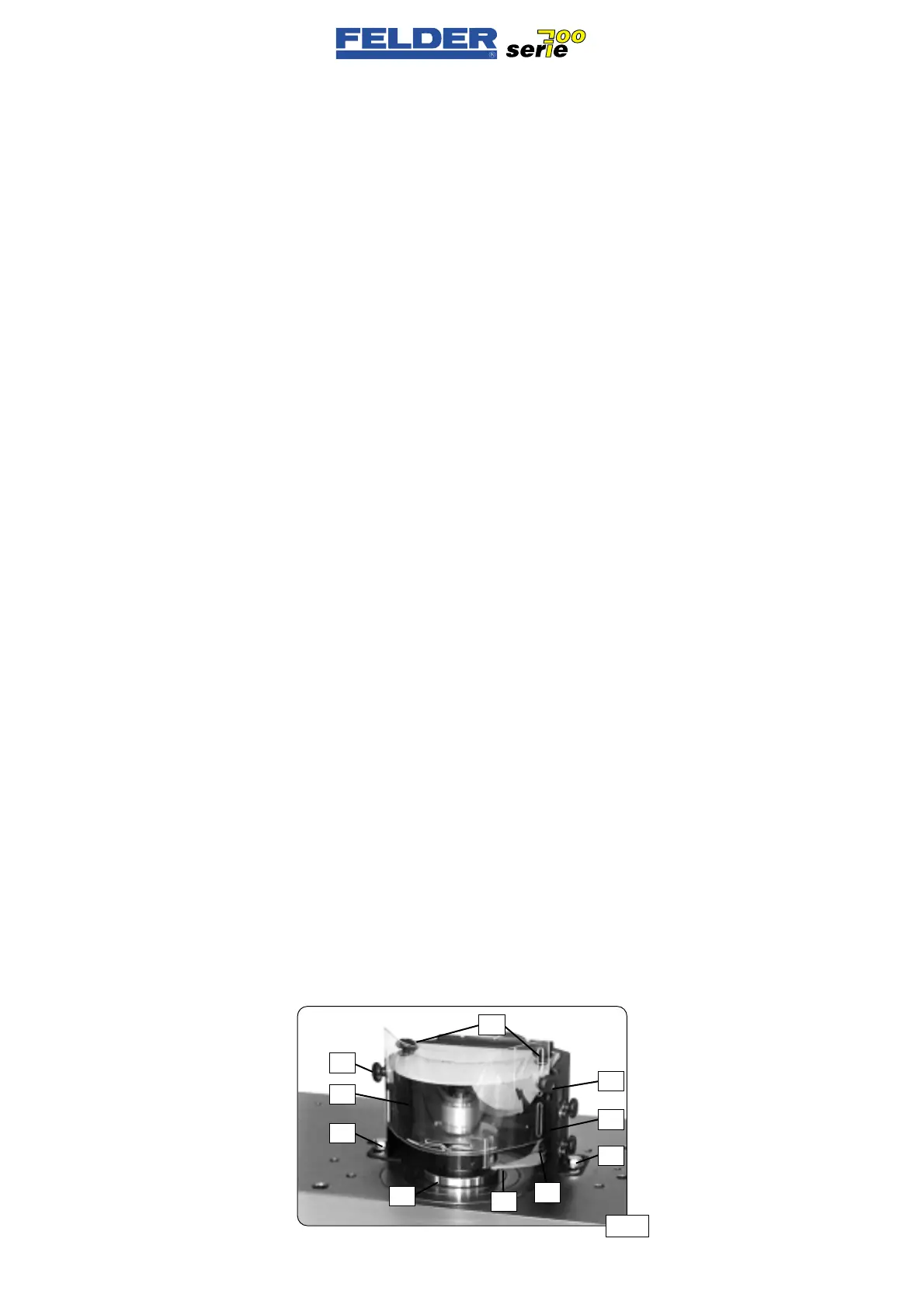
Curve shaping guard
Curve shaping is performed with a
guide ring A which is clamped on the
shaper spindle under the shaping tool
and runs on a ball bearing.
Guide rings must be chosen to suit the
shaping tool diameter.
Refer to the FELDER accessory and
tool catalog.
The curve cutting guard can be used
with both directions of rotation. When
using the second rotating direction,
the guide bar L and the brush B must
be changed over to the left side of the
guard hood.
The stop ring guard is fixed to the sha-
per table with 2 screws S.
The guide bar Lis adjusted to the
height of the guide ring A.
After opening the clamping screw K,
the guide bar L is set to the guide ring
A so a distance of max. 1-2 mm is
between the guide bar L and guide
ring A.
After opening the thumbscrews R1
and R2, the contact guard Z can be
adapted to the tool and workpiece.
The height of the contact guard Z must
be adjusted so its lower edge is 2-3
mm over the workpiece.
After opening both thumbscrews,
extend the brush B to the foremost
point of the guide ring.
F01-2.2)
Dispositivo protezione limatri-
ce curva
La fresatura curva (fresatura ad arco)
viene effettuata con un anello di guida
A, che viene bloccato sul mandrino
albero toupie con cuscinetti a sfera
sotto l’utensile di fresa.
A seconda del diametro dell’utensile
di fresatura devono essere usati degli
anelli di riferimento adatti.
Vedere al riguardo il catalogo acces-
sori e utensili FELDER.
Il dispositivo di protezione fresatura è
adatto ai due sensi di rotazione. Utili-
zzando il 2. senso di rotazione, il
listello di azionamento L e la spazzola
B sul lato sinistro della cappa di pro-
tezione devono essere smontati.
Il dispositivo di protezione fresatura
viene montato sul piano di fresatura
tramite le 2 viti S.
Il listello di azionamento L viene rego-
lato con l’altezza dell’anello di riferi-
mento A.
Dopo aver aperto le viti di serraggio
K, il listello di azionamento L viene
registrato sull’anello di riferimento A
in modo tale che tra listello L e anello
A ci sia una fessura di max. 1-2 mm.
Dopo aver aperto le viti a testa zigri-
nata R1 e R2, la protezione accesso Z
viene adattata all’utensile utilizzato e
al pezzo.
La protezione accesso Z dev’essere
regolata in altezza in modo tale che il
suo bordo inferiore si trovi 2-3 mm
sopra il pezzo.
Dopo aver aperto le due viti a testa
zigrinata, la spazzola B viene sposta-
ta in avanti fino al punto più anteriore
dell’anello di riferimento.
- 8 -
F01 V1/99 S1
F01-2.2)
Anlaufschutzvorrichtung
Das Anlauffräsen (Bogenfräsen) wird
mit einem Anlaufring A, der unter
dem Fräswerkzeug kugelgelagert auf
der Frässpindel eingespannt wird,
durchgeführt.
Je nach Fräswerkzeugdurchmesser
müssen passenden Anlaufringe ver-
wendet werden.
Siehe dazu FELDER-Zubehör- und
Werkzeugkatalog.
Die Anlaufschutzvorrichtung ist für
beide Drehrichtungen geeignet.
Bei Verwendung der 2. Drehrichtung
muß die Anfahrleiste L und die Bürste
B auf die linke Seite der Schutzhaube
ummontiert werden.
Die Anlaufschutzvorrichtung wird mit
den 2 Schrauben S am Frästisch mon-
tiert.
Die Anfahrleiste L wird in die Höhe
des Anlaufringes A eingestellt.
Nach Öffnen der Klemmschrauben K
wird die Anfahrleiste L an den
Anlaufring A so angestellt, daß zwi-
schen Anfahrleiste L und Anlaufring A
ein Spalt von max. 1-2 mm besteht.
Nach Öffnen der Rändelschrauben R1
und R2 kann der Zugriffschutz Z an
das verwendete Werkzeug und Werk-
stück angepaßt werden.
Der Zugriffschutz Z muß in der Höhe
so eingestellt werden, daß seine
Unterkante 2-3 mm über dem Werk-
stück ist.
Nach Öffnen der beiden Rändel-
schrauben wird die Bürste B bis zum
vordersten Punkt am Anlaufring vor-
gestellt.
Abb 06
R1
R2
Z
S
A
L
K
S
B
R2
 Loading...

