F01-2.3)
Changing the shaping tool
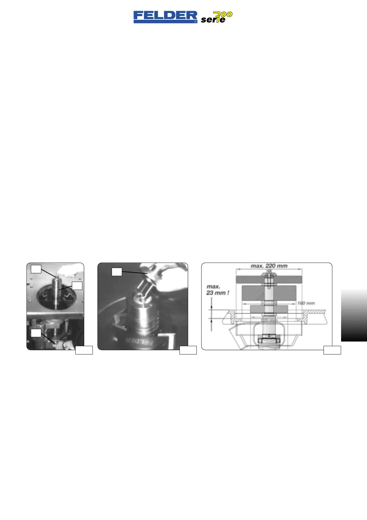
See fig. 07 - 09
Switch off main switch.
Push button S and turn the shaper
spindle until the retaining bolt locks
into place.
Hold button S and release the clam-
ping screw K.
(hexagon socket wrench, 8 mm)
Remove the spindle rings R and fit the
shaping tool to the shaft of the shaper
spindle as low as possible to prevent
vibration.
Clean the shaper spindle of dust and
chips before installing the shaping tool
to ensure that the tool seats correctly.
When replacing the spindle rings R,
ensure that adequate clamping travel
is available between the shaper spind-
le and the clamping cap (
~8 mm).
Place the shaping cap F in position,
lock the shaper spindle (press button
S) and firmly tighten the clamping
screw K.
(minimum tightening torque: 30 Nm)
The shaper spindle and its tool can be
lowered under the table by a up to
125 mm.
This permits a faster changeover to
other work operations in combined
machines.
If a larger shaping tool is installed, it
is also possible to remove the comple-
te shaper spindle from the machine.
F01-2.3)
Cambio utensili di fresatura
Vedere figg. 07 - 09
Disinserire l’interruttore principale.
Premere il pulsante S e girare il mand-
rino portafresa finché la vite di arresto
non si inserisca.
Tenere premuto il pulsante S e allenta-
re la vite di serraggio K.
(chiave per viti a brugola 8mm)
Rimuovere gli anelli del mandrino R e
posizionare più in basso possibile
l’utensile di fresatura sull’asta del
albero per evitare vibrazioni.
Prima di inserire l’utensile di fresatura,
eliminare polvere e trucioli dal albero
perché l’utensile di fresatura possa
avere una perfetta sede.
Nel rimettere gli anelli del albero R fare
attenzione che ci sia sufficiente spazio
di bloccaggio tra mandrino portafresa
e calotta di serraggio (
~8mm).
Mettere la calotta di fresatura F, bloc-
care il mandrino (premere il pulsante
S) e stringere la vite di serraggio K.
(Coppia di serraggio minima: 30 Nm)
L`albero toupie può essere inserito
sotto alla tavola con utensili fissati fino
a un diametro max. 125 mm.
Nelle macchine combinate, questo
permette un rapido cambio lavorazio-
ne nel passare ad altre fasi di lavoro.
Se dovesse essere fissato un utensile di
fresatura più grande, è anche possibi-
le togliere tutto il albero dalla macchi-
na.
- 9 -
F01 V1/99 S1
F01
F01-2.3)
Fräswerkzeugwechsel
Siehe Abb. 07 - 09
Hauptschalter ausschalten.
Knopf S drücken und Frässpindel dre-
hen, bis Arretierbolzen einrastet.
Knopf S gedrückt halten und Klemm-
schraube K lösen.
(Inbusschlüssel 8mm)
Spindelringe R entfernen und Fräs-
werkzeug so tief wie möglich auf den
Schaft der Frässpindel setzten, um
Vibrationen zu vermeiden.
Vor dem Einsetzen des Fräswerkzeu-
ges die Frässpindel von Staub und
Spänen reinigen, um einen einwand-
freien Sitz des Fräswerkzeuges zu
erreichen.
Beim Wiederaufsetzen der Spindelrin-
ge R darauf achten, daß genügend
Klemmweg zwischen Frässpindel und
Klemmhut liegt (
~8mm).
Fräshut F aufsetzten, Frässpindel arre-
tieren (Knopf S drücken) und Klemm-
schraube K fest anziehen.
(Mindestanzugsmoment: 30 Nm)
Die Frässpindel kann mit eingespann-
ten Werkzeugen bis max. 125 mm
Durchmesser unter den Tisch versenkt
werden.
Dies ermöglicht bei Kombimaschinen
ein schnelleres Umrüsten auf andere
Arbeitsgänge.
Sollte ein größeres Fräswerkzeug ein-
gespannt sein, besteht auch die Mög-
lichkeit, die ganze Frässpindel aus der
Maschine zu nehmen.
Abb 10Abb 08Abb 07
S
K
R
F
 Loading...

