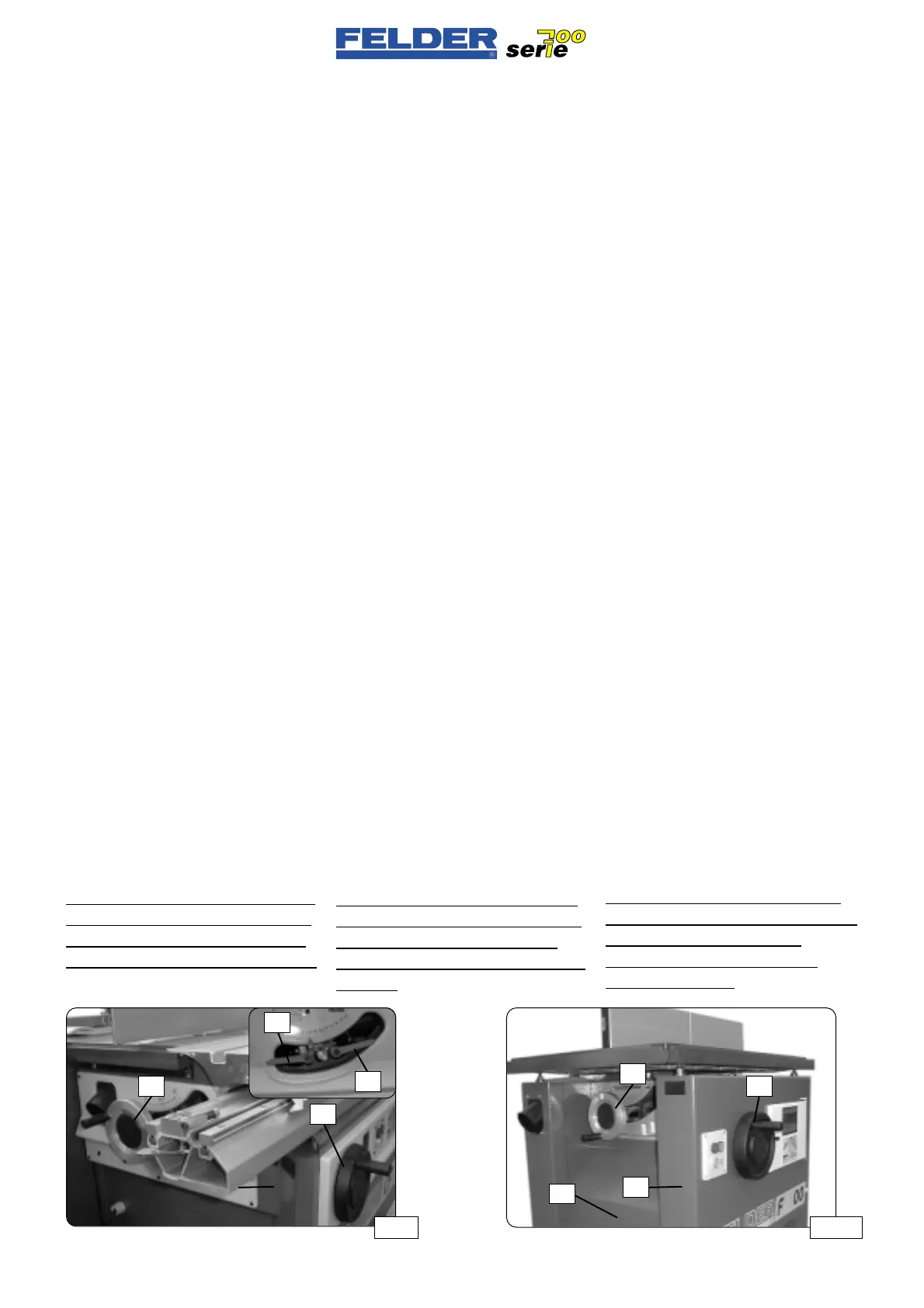
F01-2.8)
Height adjustment of shaper
spindle
The shaper spindle can be continuous-
ly adjusted in height and completely
lowered under the table.
Open the height clamping lever K1 by
half a turn and adjust the shaper
height with the handwheel H1.
One turn equals 2 mm.
Always adjust the height from a lower
to a higher setting to compensate for
the reversing play of the height adjust-
ment spindle.
Lock the height adjustment with the
height clamping lever K1.
See fig. 16.
F01-2.9)
Tilting the shaper spindle
The shaper spindle can be tilted back-
ward continuously from 90° to 45°.
This brings you great savings on tools.
Open the angle clamping lever K2 by
half a turn and adjust the shaper
angle with the handwheel H2.
See fig. 16 / 16A
One turn equals 1°.
Always adjust the angle in the same
direction to compensate for the rever-
sing play of the worm.
The value can be read off directly
from the degree scale S.
Lock the angle adjustment with the
height clamping lever K2.
For a precise readout of the shaping
spindle angle and shaping height, we
recommend the digital handwheel
(order no. 01-0-200) in our accessory
program.
F01-2.8)
Regolazione in altezza del
albero toupie
Il albewro toupie può essere regolato
continuamente in altezza e inserito
completamente sotto alla tavola.
Aprire la leva di serraggio altezza K1
di mezzo giro e regolare l’altezza
della fresatrice con il volantino H1.
Un giro corrisponde a 2 mm.
Regolare sempre dal basso l’altezza
della fresatrice per poter equilibrare il
gioco dei filetti del mandrino di rego-
lazione altezza.
Fissare la regolazione in altezza con
la leva di bloccaggio altezza K1.
Vedere fig. 16
F01-2.9)
Inclinazione dell’albero toupie
Il albero toupie può essere orientato
indietro in modo continuo da 90° a
45°. Questo è molto vantaggioso spe-
cialmente per limitare l’usura degli
utensili.
Aprire di mezzo giro la leva di bloc-
caggio angolo K2 e regolare l’angolo
di fresatura con il volantino H2 .
Vedere figg. 16 / 16A
Un giro corrisponde a 1°.
Regolare sempre l’angolo dalla stessa
direzione per equilibrare il gioco del
filetto della vite senza fine.
L’angolo può essere letto direttamente
sulla scala graduata S.
Fissare la regolazione dell’angolo con
la leva di bloccaggio altezza K2.
Per una precisa lettura dell’angolazio
-
ne dell’albero toupie vi raccomandia-
mo il volantino digitale (n. ord.01-0-
200) del nostro programma accessori.
- 14 -
F01 V1/99 S1
F01-2.8)
Höhenverstellung der Fräs-
spindel
Die Frässpindel kann in der Höhe stu-
fenlos verstellt werden und komplett
unter den Tisch versenkt werden.
Höhenklemmhebel K1 um eine halbe
Umdrehung öffnen und Fräserhöhe mit
dem Handrad H1 einstellen.
Eine Umdrehung entspricht 1 mm.
Die Fräserhöhe immer von unten
anstellen, um das Gewindespiel der
Höhenverstellspindel auszugleichen.
Höhenverstellung mit dem Höhen-
klemmhebel K1 fixieren.
Siehe Abb. 16
F01-2.9)
Schwenken der Frässpindel
Die Frässpindel kann stufenlos von
90° bis 45° nach hinten geschwenkt
werden. Das bringt speziell für die
Einsparung von Werkzeugen sehr
große Vorteile.
Winkelklemmhebel K2 um eine halbe
Umdrehung öffnen und Fräserwinkel
mit dem Handrad H2 einstellen.
Siehe Abb. 16 / 16A
Eine Umdrehung entspricht 1°.
Den Winkel immer von derselben
Richtung anstellen, um das Gewinde-
spiel der Schnecke auszugleichen.
Der Winkel kann direkt an der Grads-
kala S abgelesen werden.
Winkelverstellung mit dem Höhen-
klemmhebel K2 fixieren.
Für eine genaue Ablesung des Fräs-
spindelwinkels und der Fräshöhe emp-
fehlen wir das Digitalhandrad
(Best.Nr.01-0-200) aus unserem
Zubehörprogramm.
Abb 16 Abb 16A
H1
H1
H2
H2
K1
K2
K1
K2
 Loading...

