F01-3.6)
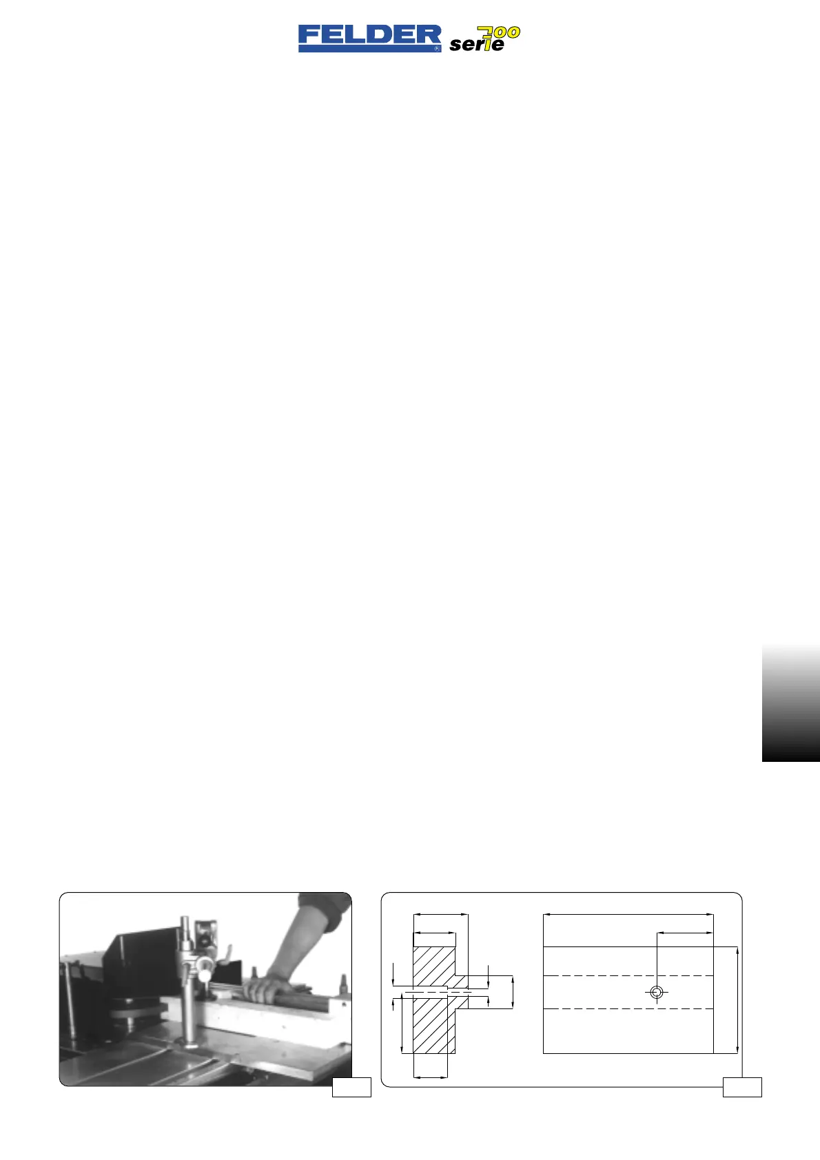
Mortise and tenon shaping
See fig. 26 / 27
The mortise and tenon guard and
tenoning plate are required for morti-
se and tenon work.
Both are available as accessories.
Mount the mortise and tenon clamping
set according to the included assembly
instructions.
The workpiece must be securely clam-
ped to the sliding table or the slotting
plate, close to the outer tool diameter,
with the eccentric hold-down.
The slotting plate must be mounted in
the center of the sliding table so that
the sliding table guide elements are
located directly below it. This gives the
sliding table sufficient stability in the
working area.
The upper cover of the guard must be
adjusted as close to the tool as possi-
ble to prevent contact with the rotating
tool.
Be careful to select the proper (lower)
speed before switching on.
See the diameter-speed diagram.
A wooden backup is used as the rear
workpiece support and is mounted in
front of the 90° fence. This backup
piece must be replaced after several
slotting operations (see drawing).
F01-3.6)
Tenonatura e intagliatura
Vedere figg. 26 / 27A
Per la fresatura di tenoni e intagli è
necessario utilizzare la cappa di pro-
tezione tenonatura e intagliatura, non-
ché la piastra di sovraspinta.
Ambedue sono disponibili come
accessorio.
Montare il set di bloccaggio per teno-
natura e intagliatura secondo le istru-
zioni di montaggio allegate.
Il pezzo dev’essere bloccato con il
pressore eccentrico sulla tavola scorre-
vole e/o la piastra di sovraspinta vici-
no al percorso della lama.
La piastra di sovraspinta dev’essere
montata nel centro della tavola scorre-
vole, in modo che gli elementi di
guida della tavola le si trovino esatta-
mente sotto e quindi venga garantita
una sufficiente stabilità della tavola
stessa nel campo di lavoro.
La copertura superiore della cappa di
protezione dev’essere posizionata più
vicino possibile all’utensile per evitare
il contatto con l’utensile girevole.
Prima dell’inserimento, controllare
specialmente che sia impostato il cor-
retto numero di giri (basso).
Vedere diagramma diametro-numero
di giri.
Come appoggio posteriore del pezzo
viene utilizzato un legno fessurato,
montato davanti sul guidapezzo a
90°. Questo legno dev’essere sostitui-
to come da schema dopo alcune ope-
razioni di intagliatura.
- 19 -
F01 V1/99 S1
F01
F01-3.6)
Zapf- und Schlitzfräsen
Siehe Abb. 26 / 27
Zum Fräsen von Zapfen und Schlitzen
wird die Zapf- und Schlitzschutzhaube
sowie die Überschubplatte benötigt.
Beides ist als Zubehör erhältlich.
Das Zapf- und Schlitzspannset ent-
sprechend der mitgelieferten Aufbau-
anleitung montieren.
Das Werkstück muß mit dem Exzen-
terniederhalter fest auf dem Schiebe-
tisch bzw. der Überschubplatte nahe
dem Messerflugkreis geklemmt wer-
den.
Die Überschubplatte muß in Schiebe-
tischmitte montiert werden, sodaß sich
die Schiebetischführungselemente
genau darunter befinden und so aus-
reichende Stabilität des Schiebetisches
im Arbeitsbereich gewährleistet ist.
Die obere Abdeckung der Schutzhau-
be muß so nahe wie möglich an das
Werkzeug angestellt werden um Kon-
takt mit dem rotierenden Werkzeug zu
vermeiden.
Vor dem Einschalten ist besonders auf
die richtige (niedere) Drehzahl zu
achten.
Siehe Durchmesser-Drehzahl-Dia-
gramm.
Als hintere Werkstücksauflage wird
ein Schlitzholz verwendet das vorne
am 90°-Anschlag montiert wird . Die-
ses Schlitzholz müssen Sie nach eini-
gen Schlitzarbeiten lt. Skizze erneu-
ern.
Abb 26
 Loading...

