wwwwww
..
ffeennddeerr..ccoomm
✧
wwwwww
..mmrrggeeaarrhheeaadd..nneett
13
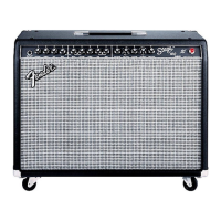
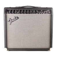
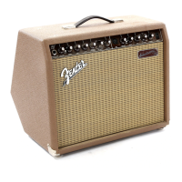
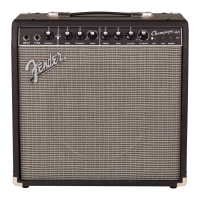
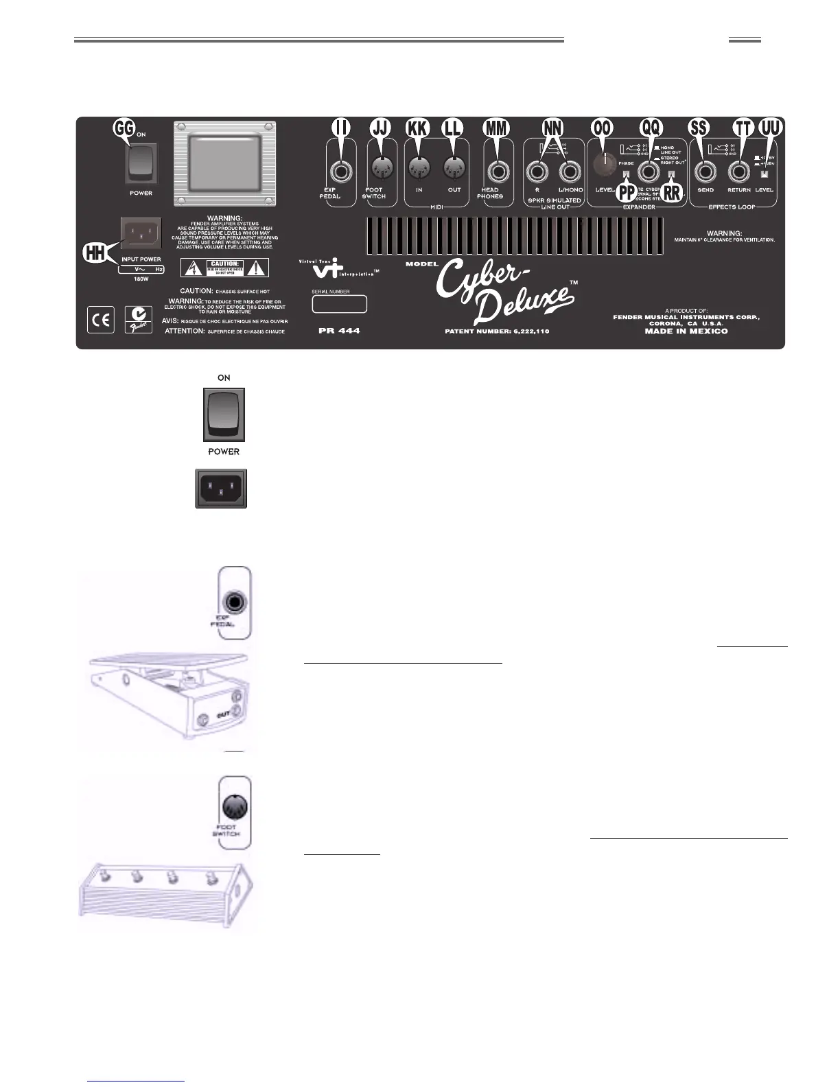
Rear Panel Overview
GG. POWER
Switches Power ON or OFF to the Cyber–Deluxe™ amplifier.
HH. IEC POWER CORD SOCKET
Connection for the included power cord. Connect to a grounded AC outlet
in accordance with the voltage and frequency rating listed on the rear panel
of the unit.
II. EXPRESSION PEDAL JACK
Connection for a standard expression foot pedal (optional) used to remotely
control the function of any front panel numbered knob, except for TRIM {B}.
It can also be assigned to control the primary Reverb, Modulation or Delay
effect parameter. The assignment is preset programmable (see Expression
Pedal—Parameter Assignment on page 26).
JJ. FOOTSWITCH JACK
Connection for the included Fender
®
4–button footswitch used to access
four favorite presets hands-free. The front panel footswitch LEDs {X}
indicate active footswitch buttons (see 4–Button Footswitch—Preset
Assignment on page 25).
NOTE: For best results, use the supplied 5-pin DIN cable for connection.
Use of some MIDI–type cables can cause erratic footswitch operation.
RR
RR
ee
ee
aa
aa
rr
rr
PP
PP
aa
aa
nn
nn
ee
ee
ll
ll
OO
OO
vv
vv
ee
ee
rr
rr
vv
vv
ii
ii
ee
ee
ww
ww
 Loading...